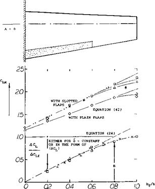
CHARACTERISTICS IN THREE-DIMENSIONAL FLOW
In wings with finite span the induced angle of attack and the induced drag have important effects upon the performance of flaps.
Limits of Circulation. Any lifting wing deflects a stream tube of air with an effective diameter approximately equal to its span. In engineering language the corresponding downwash angle at the “lifting line” corresponds to the second term in
dc*°/dCL^ 10 + 20/A (20)
“Base” Drag. Behind flaps with separated flow pattern there is a negative base-type pressure. Tests reveal that the magnitude of this pressure behind split flaps deflected 6СГ, corresponds to the coefficients.
C p = -0.55 in two-dimensional flow (between walls)
= —0.60 in wings with full-span split flaps
= —0.45 in wings with part-span split flaps
So, there is a difference in drag due to flaps installed on finite wings. Assuming that the negative pressure has some boundary-layer controlling effect upon the upper side of the airfoil, there is also a possibility that in part-span flaps, quantities such as (aCu) and CLX are somehow lower than in two-dimensional conditions. The negative pressure in full-span split flaps may be explained by tip vortex suction.


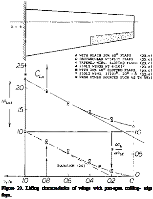
![]() Part-Span Flaps. Figure 20 shows how the overall lift of a wing is reduced as a function of the flap-span ratio. Since the presence of the fuselage usuallymakes it impossible to deflect wing flaps in the very center of the airplane, a function is also included showing how lift decreases when cutting away from the center. Flaps are usually used up to some 0.6 of each half span; and the cutout due to fuselage may amount to 0..1 b. The resultant lift increment of an airplane as derived from the graph, may be some 70% of the two-dimensional values found in the first section of this chapter. This influences the performance in three ways:
Part-Span Flaps. Figure 20 shows how the overall lift of a wing is reduced as a function of the flap-span ratio. Since the presence of the fuselage usuallymakes it impossible to deflect wing flaps in the very center of the airplane, a function is also included showing how lift decreases when cutting away from the center. Flaps are usually used up to some 0.6 of each half span; and the cutout due to fuselage may amount to 0..1 b. The resultant lift increment of an airplane as derived from the graph, may be some 70% of the two-dimensional values found in the first section of this chapter. This influences the performance in three ways:
• the optimum average lift coefficient is reduced,
• the optimum flap deflection is reduced,
• the induced drag of the wing is increased.
The induced drag will be considered under “takeoff’ and “climb”. The results of part-span analysis (23,c) are plotted in figure 20. The subscript “f ’ indicates values for a wing with full-span flaps. The ratio ACL/ACuf can be evaluated for constant angle of attack such as of = zero. For small angles of deflection:
ACL/ACLf =Cl6/CL6, (23)
where CL5 =: dCL/dS. Theory is well confirmed by experimental points. Variations of the function with platform (taper ratio) and/or aspect ratio are predicted to be small. For flap-span ratios up to 0.5 halfspan, it can be written:
ACLjACLi я 1.25 (b{ /b) (24)
(20) Characteristics of Fowler and similar flaps:
a) Wenzinger, Pressure Distributions 20 to 40% Flaps, NACA TRpt 620 (1938).
b) Platt; Wing Including Loads, Downwash, Takeoff; NACA TRpt 534 (1935).
c) Wenzinger, Venetian-Blind Flaps, NACA TRpt 689 (1940).
d) Wenzinger, 23012 Airfoil With Auxiliary Tabs, NACA TRpt 679 (1939).
e) H. D. Fowler, Variable Lift, “Western Flying”, Nov 1931 p 31.
0 Harris, 23012 Airfoil With 2 Flaps, NACA W Rpt L-441 (1940).
g) Fullmer, Foil Sections for Lockheed “Vega”, NACA W Rpt L-681 (1945).
Part (b) – Outboard flaps (ailerons).
(21) Rettie, Velocity Around Airfoil Nose, ARC RM 3027 (1957).
Outboard Flaps. The results in part (b) of figure 20, gives the influence of a fuselage on the performance of outboard flaps. It might tentatively be assumed that the loss of lift is
(ACL/ACLf ) = (b-bf)/b (25)
where b – bf = flap cutout in the center of the wing. For determining maximum lift, a similar equation might be used.
Lift Distribution. The problem with part-span wings, is the fact that optimum conditions (providing maximum L/D) in the flapped and the plain parts of the span may not be obtained at one and the same angle of attack. For the modest angle of deflection <5 = 20 , the lift increment due to an average flap is already 0.7
0. 7, while the difference in the optimum coefficient between flapped and plain parts of the wing, only amounts to ACU & 0.2. Thus, a compromise must be accepted and the optimum angle of flap deflection may only be in the order of 10 , rather than 30 or even 40° as suggested by two-dimensional flap investigations. In fact, all the disturbances and interruptions of the lift distribution by supporting and actuating devices, by the fuselage and by engine nacelles, make the more advanced wind-tunnel results questionable, particularly as far as flight performance is concerned.
|
|
|
|
|
Figure 21. Examples for the flow pattern past slotted-flap configurations as observed in a water tunnel at RCf above 10 . |


