Elements of propulsion engines
3.7 Rather than describing details of actual engines, we shall concentrate in this Section on certain basic types of flow which are characteristic of the aerodynamics of propulsion and may help to explain some of the design features of propulsion engines. We shall discuss
flows with energy addition, either in the form of heat or mechanical energy;
air intake and nozzle exit flows of engines surrounded by fairings; and
some very simple complete engines, to see how the elements can be put together.
Consider first two hypothetical flows past a поп-ducted burner disc, where heat is assumed to be added at constant area. We know in advance that there can be no thrust force because there is no solid body to take it. A burner disc in a subsonic stream produces a flow like that sketched in Fig. 3.17. Pressure and density increase as the air approaches the disc. They both fall again by a larger amount during heat addition, whereas the temperature increases. Behind
Means for Generating Lift and Propulsive Forces
![]()
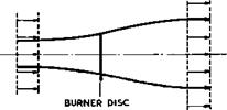 |
the burner, the pressure rises to the undisturbed value but the density remains below and the temperature above their respective undisturbed values. The velocity of the air falls as it approaches the burner; it is then suddenly increa-
„ Fig, 3,17 Subsonic flow past a burner
 |
 |
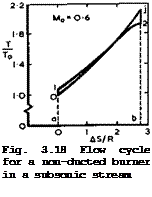
sed and falls again behind the burner to the freestream value. Thus no jet is formed, which is consistent with the fact that the burner cannot take any forces, The flow properties imply that the streamtube that passes through the disc increases all the way and that the burner produces nothing but hot air behind it. This state of affairs is fortunately revealed at once by the flow
cycle for the air that takes part in the combustion process, as shown in Fig. 3.18. We find that the curves in the cycle diagram cross over and that all the heat supplied is again rejected to the surroundings. Hence no available mechanical energy is left.
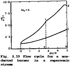
If the flow is supersonic, the non-ducted burner may be regarded as a detonation wave standing on a disc normal to the mainstream. Such a detonation wave may be interpreted for our purpose as the combination of a normal shockwave with heat addition at constant area. Thus the change of state of the air from far upstream to the beginning of combustion may be thought of as including the non-isentropic compression by the shockwave between 0 and 1, as shown in Fig. 3.19, and heat addition at constant area between 1 and 2. Although we know that again no thrust force is produced, this is not now revealed by the flow cycle for that part of the airstream subjected to these changes of state; a genuine jet with increased velocity is produced, the thermal efficiency is quite good (0.37 in the example shown), and the propulsive efficiency (0.34) would suggest that the available propulsive work is considerable. The explanation for this apparent paradox has been given by
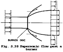
К Oswatitsch (1959): it can be seen by inspection of the actual flow, as indicated in Fig. 3.20. The expanding flow behind the burner and the widening jet require that at least one shockwave is generated in the external stream. Hence
a strong interaction with the external stream occurs and work is done on it by the heat-addition process. The entropy is increased not only in the jet but also in the external stream, and the associated effects cancel each other out exactly: the burner produces hot air and shochwaves, This then is a case where the assumption d’w ■ 0 cannot be made and where the basic thrust equation is not true. Thus the example of the non-ducted burner demonstrates in a drastic manner that there can be strong interactions between the flow of air that takes part in the heat-addition process and the external stream, and that the propulsive efficiency of the onedimensional flow cycle is not a measure for the actual propulsive force obtained for the combined flowfield. This defines a fundamental aerodynamic problem of propulsion, especially of heat addition at supersonic and hypersonic speeds, and we shall have to come back to it later in Section 8.5.
It may be somewhat reassuring to consider next a counterpart to these flows, namely, one where only mechanical energy is added to the flow, instead of heat. This means we ignore that part of the propulsion system where heat is converted into mechanical energy. This process can be interpreted as a non-ducted airscrew3or propeller, where heat is converted into work and taken out by a shaft by means of a piston engine. Consider the ideal propeller in a subsonic
WITHOUT FRICTION
|
|
|
WITH FRICTION |
|
I* T To I- o- |
 |
О о O-l О о O-l 0*2
As/R As/R
Fig. 3.21 Flow cycles of a propeller in a subsonic stream
LIVE GRAPH
Click here to view
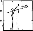
flow without friction. There is no supply of heat, q = 0 ; but mechanical work is done by external means and transferred to the propeller, w Ф 0. Neither enthalpy of the air not the entropy in the slipstream is different from those upstream: Tj = Tq and sj = Sq. The whole of the energy supplied is
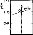
eventually transferred into kinetic energy in the jet. The propulsive efficiency is not unity since the kinetic energy is only partly used to produce thrust. The efficiency is given by the Froude efficiency of (3.74). All the changes of state of the air follow a single isentropic curve, as indicated in Fig. 3.21. Up to the propeller disc, 0 •+• 1, pressure, density, and also temperature decrease. In the passage through the propeller disc, 1 2, each of
these parameters rises suddenly. As the pressure decreases gradually to pg behind the propeller, 2 -*■ j, density and temperature approach their initial values at 0. The diagram in Fig. 3.21 shows that no work is done by the flow, as the curve encloses no area. The air only serves as a converter of the mechanical energy in the propeller shaft into kinetic energy in the slipstream.
The streamline pattern of this flow is such that the streamtube containing the air that passes through the propeller disc narrows all the way and looks, at first sight, like the reverse of that in Fig. 3.17, except that a proper jet is formed. The upstream influence of the propeller is such that the velocity increases from Vq to some higher value just upstream of the disc; and the downstream influence produces a further increase to Vj in the Trefftz plane. By the application of Bernoulli’s equation separately to the flow upstream and downstream of the propeller, we find that the average axial velocity Vp at the propeller is the mean of the velocities far upstream and far downstream:
Vp = i(V0 + Vj) (3.82)
But there is a sudden increase of the axial velocity component at the propeller disc so that there must be a velocity jump also at the edge of the stream – tube of the slipstream all the way downstream of the propeller. This means that there exists, in this model of the flow, a vortex sheet around the slipstream, composed of elemental ring vortices which are shed from the tips of the (infinite number of) propeller blades and continued as bound vorticity along the blade, around which there is a circulation. This flow model is thus closely analogous to that of classical lifting wings, which was discussed in Section 3.2.
With a real propeller, some energy is lost due to frictional forces at the propeller blades, leaving a viscous wake behind. It is still true that q =* 0, w ф 0, but now Tj Ф Tq. Both entropy and enthalpy are now greater in the slipstream than in the undisturbed flow: T. > Tq. Thus only part of the ener
gy supplied is converted into kinetic energy and the rest is wasted on an increase of the enthalpy in the slipstream. The changes of state of the air are also shown in Fig. 3.21. The entropy increases when the air passes through the propeller disc. The area aOjba represents the energy wasted due to friction, which appears as a temperature increase in the flow downstream. The efficiency is naturally less than that of the ideal propeller. Here then is a flow cycle where a genuine thrust force is produced and we know where it acts: on the blades of the propeller itself, again in close analogy to the generation of lift on classical aerofoils.
We learn from this example of the propeller that a thrust force is obtained only when the specific momentum in the Trefftz plane is increased, at the same pressure far upstream and downstream. Further, the generation of a thrust force is associated with the shedding of a vortex sheet and this, in turn, requires the presence of a solid body from which it originates. This should apply
also to the flow with direct heat addition and we must ask ourselves, therefore, what form such a body should take.
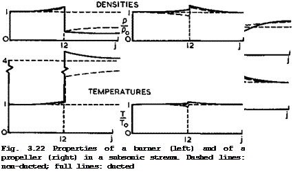 |
A simple shape of a solid body to think of is a cylindrical fairing that surrounds the burner or the propeller, so that we have energy addition in a duct. This leads us to the somewhat more realistic engine concepts of ducted burners, or ramjets, and ducted propellers, or fanjets. To be quite clear about
the properties of propulsion systems with heat supply and with supply of mechanical energy, Fig. 3.22 has been prepared to summarise the aerodynamic and thermodynamic characteristics at subsonic speeds of non-ducted and ducted burners and propellers. For simplicity, the ducts have zero length, but it is assumed that there is a circulation around them, which changes the velocity field inside the duct. The main streamlines, the variations of velocity and pressure, and the thermodynamic parameters density and temperature are shown.
The numerical values have been chosen so that the overall thrust is the same in all cases for Mg – 0.63 (except for the non-ducted burner where the thrust is zero). To obtain these flows, all that must be assumed is that the fairing is suitably shaped so that the mass flow through the duct is regulated in an appropriate manner and that the thrust force can act on it.
What the circulation around the fairing should be and how the fairing should
|
Fig. 3 .23 Subsonic flows past a burner – ducted and non-ducted |
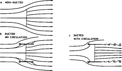
be shaped so as to be able to sustain a thrust force can be explained by considering the special case of heat addition to a subsonic stream in more detail. The basic flow without a duct is sketched in Fig.3.23(a). The sudden increase in velocity at the burner disc is indicated by a corresponding increase in the density of the streamlines (which signifies a certain analogy between flows with heat addition and flows with mass addition). But we know that no jet is formed and that, consequently, there is no vortex sheet dividing the air which goes through the burner from that which flows around it. If we put a cylindrical fairing around the burner, as in Fig. 3.23(b), the fairing is inclined to the local flow direction in a manner similar to the plate at an angle of incidence shown in Fig. 2.14(a). In an inviscid fluid, we can then conceive a flow like that shown in in Fig. 3.23(b), where the flow pattern is changed only locally by the fairing and where there is still no jet and no axial force on the fairing. The air flows round both the leading and trailing edges and the suction forces there are equal and opposite. If we now consider what may happen in a real flow, by the sudden application of viscosity as argued in Section 2.4, and if we want to satisfy the Kutta condition of smooth outflow at the trailing edge of the fairing, then a time-dependent and possibly periodic shedding of vorticity would be a possible solution, as indicated in Figs.2.14 and 3.23(c). Only in special cases could the fairing be shaped in such a way that the pressure in the exit plane would be equal to the undisturbed pressure Pq so that a smooth steady vortex sheet could be formed. In general and on time-average, a jet will now emerge and the resulting thrust force will act as a suction force at the leading edge of the fairing. There is now a circulation around the fairing, and the shape of the fairing will have to have a rounded leading edge to realise the suction force, in the same manner as on twodimensional aerofoil sections (Fig. 3.4). We must expect that the periodic vortex cores around the jet will make a noise. In any real subsonic engine with heat addition, conditions are fundamentally similar to those indicated in Fig.3.23 (c). The flow through the duct is normally regulated by control of the exit area, by means of the Kutta condition, but important changes occur also at the inlet.
In practice, the fairing may often be regarded as an annular aerofoil with circulation. In some cases, e. g. with ducted fans, the length is comparable to the diameter. The design of such annular aerofoils is closely related to that of wings amd approximate design methods have been developed. We refer to some recent papers on the matters by C Young (1969), W Geissler (1973), and V Krishnamurthy & N R Subramanian (1974), where further references may be found. In a complete design, the flow induced by the burner, or fan, inside the fairing is also taken into account. Depending on the initial circulation around the annular aerofoil, the ducted fan may be designed to have a larger mass flow (than the fan alone) at low speeds and hence an augmented thrust, absorbing more power; or a lower mass flow at high speeds to reduce the Mach number at the blades. In either case, the viscous drag of the fairing must be taken into account. The overall propulsive efficiency has a maximum which is reached when this viscous drag and the loading on the fan are correctly balanced: if the fan loading is too low, the viscous drag will dominate and reduce the efficiency; if it is too high, the fan losses themselves will reduce the efficiency. Although the physical principles of such ducted devices have been clarified some time ago (see e. g. D KUchemann (1941) and (1942)), some practical applications have appeared only recently.
|
b STATIC CONDITIONS |
|
Fig. 3.24 Subsonic flows into an air intake |
Actual jet engines, such as turbojets and fanjets, combine the addition of heat and of mechanical energy. A multistage compressor is added upstream of
the combustion chamber, to increase the pressure at combustion, and a turbine is added downstream of the combustion chamber, to drive the compressor. The gas generator – i. e. the compressor, the combustion chamber, and the turbine – is then surrounded by a fairing which is so long in relation to its diameter that the flow into the inlet and around the nose of the intake of the fairing can be treated separately from the flow inside the fairing (for detailed information, see e. g. R Hermann (1956), J C Eward (1957), J Fabri
(1958) , and AGARD Conference Proceeding CP-91 (1971)). The same applies to the nozzle flow at the end of the fairing. This leads to a very convenient separation of problem areas.
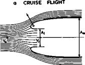
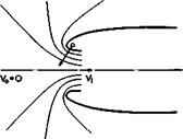
We now arrive at the concept of a subsonic intake flow, as sketched in Fig.
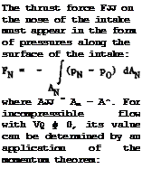
3.24, where the flow is uniform in some inlet plane A£ with a velocity V^. Roughly, Vj might be kept the same under all flight conditions, whether the flight speed Vq is high or even zero, so as to deliver the same mass flow to the gas generator inside the fairing (we igftore here density changes brought about by operation at different altitudes). We assume that the fairing is long enough for the flow over the outer surface to come back to the undisturbed velocity Vq at some point where the fairing is assumed to be cylindrical, with the maximum cross-sectional area A_. Thus the inlet flow pattern may vary a great deal. Near the maximum speed of the aircraft, there may be a definite retardation of the flow ahead of the inlet, Fig. 3.24(a), while under static conditions (V0 =0), the air approaches the inlet from all directions, Fig. 3.24(b). The flow is closely related to that around the nose of a classical aerofoil section (Fig. 3.4), but the range of flow conditions is much wider. Each section of the fairing experiences an aerodynamic force which is inclined forward. The component normal to the mainstream affects, in general, only the stressing of the fairing, but the streamwise (thrust) component may make an appreciable contribution to the thrust-drag balance of the whole power unit.
![]() (3.83)
(3.83)
(3.84)
This relation is a direct counterpart to (3.30) for the tangential force on classical wings. To obtain a genuine thrust force, the velocity over the outer surface of the intake must be greater locally than the mainstream velocity, and p^ < Pq. On the other hand, the local velocities should exceed the flight velocity as little as possible if the intake is to be designed to reach a high critical Mach number. Clearly, the velocities Vjj are least for given values of A£ and V^/Vq if the shape of the intake is such that VN is uniform over the whole curved outer surface so that Vv0 = W/Vq is the constant velocity ratio there. In this case, the integral in (3783) can be eva-
![]() (3.85)
(3.85)
using (3.84). This relation shows that a certain minimum frontal area, or thrust area, is needed to keep the external velocities within given limits. Every inlet opening, therefore, requires a surrounding fairing with a definite thickness, which must be the greater the smaller the velocity increments are allowed to be. Thus we come to the, perhaps, surprising conclusion that high critical Mach numbers require thick intake watts, that is, small values of
W ’
We note that these relations hold for intakes of any cross-section, including twodimensional, circular, or threedimensional shapes. Actual shapes with p„
■ constant have been calculated for twodimensional intakes by P Ruden (1940), and approximate shapes have been devised for circular air intakes by D KUche – mann & J Weber (1940) and (1953), D D Baals, N F Smith & J В Wright (1949).
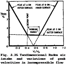
Note that, so far, corresponding design calculations have not yet been made for aerofoils and wings. General threedimensional shapes for air intakes with constant-pressure contours can also be determined experimentally by observations of cavitation bubbles (see H Reichardt (1944)). All these shapes present us with an interesting aspect of the general design problem: they might be called optimum shapes for the precise design condition but, to achieve this, the nose shape must be rather sharp, with a very small nose radius, so that these shapes are very sensitive to any changes in the flow conditions. A small change either way in V^/Vq, say, may move the attachment line around the nose in such a way that a very high suction peak occurs, either on the inner or on the outer surface, with a subsequent adverse pressure gradient which the boundary layer is not able to negotiate, and hence the flow separates. For a two-

LIVE GRAPH
 |
Click here to view
dimensional Ruden intake, these changes can be calculated and some results are shown in Fig. 3.25. These indicate how small the "working range" is (the actual working range will be somewhat larger than that shown in Fig.3.25 since some suction peak can be allowed before flow separation occurs). As a general principle, such sensitive designs with a very limited working range are not acceptable in practice. This example shows very clearly that we must make it a rule to check every design principle with a view to the off-design behaviour which the resulting shapes can be expected to have.
The case of air intakes shows us also one possible way in which such shortcomings can be overcome. Evidently, the rate of growth of suction peaks in off – design conditions depends on the radius and bluntness of the nose, and rounding – off the nose should make the intake less sensitive and widen its working range. This has been proved in practice by a series of air intakes designed in this way (D KUchemann & J Weber (1940) and (1943)). The pressure distribution along the outer surface cannot then be uniform, and the local velocity must be higher in some places than that over the corresponding constant-pressure contour. This does not invalidate (3.86), and the "greater-than" sign then applies. This means, in turn, that the velocity exceeds the speed of sound earlier, i. e. at a lower value of the flight speed, and that a looal supersonic region has already been formed over part of the outer surface when the optimum intake just becomes critical. But whereas the drag of the latter tends to rise steeply when the critical Mach number is exceeded, the drag of the former may rise only very little: for an appreciable range of supercritical Mach numbers, the local supersonic region is terminated by a shockless recompression or by a weak shockwave, so that the entropy increase is small or nearly zero (see also Section 5.2). Thus the rounded air intakes can be operated efficiently well beyond their critical Mach numbers. This is thus a design principle of practical value; to allow supercritical regions of this kind to develop from "peaky" pressure distributions is now common practice also on aerofoils and on wings. This was first demonstrated on air intakes by H Ludwieg (1943), but there is still no complete and rational design procedure.
In all cases where a retardation of the flow into the fairing is required, as for example in Fig. 3.23(c), where the velocity Vg at the burner, say, should be smaller than Vq and the pressure higher than pg, the aerodynamic load on the outer surface of the intake can be relieved by incorporating a subsonic diffuser downstream of the narrowest cross-section A^ of the intake so that the burner area Ag > A^. The pressure rise then takes place partly in the freestream upstream of the inlet (external compression – ram effect) and partly in the duct (internal compression). Momentum considerations which led to (3.84) still apply, and the total thrust force on the intake and on the walls of the diffuser is given by
![]()
![]()
![]()
![]() (3.87)
(3.87)
(3.88) and this can be smaller than that of (3.84), for a given value of V^/Vq, if A^/Ag < 1, that is, if we compare an intake without diffuser and mass flow
pVjA^ with an intake with diffuser and the same mass flow pVgAg. Part of the thrust load is then carried in the diffuser, and the design of the actual intake may be eased considerably. A diffuser is incorporated in most practical cases, not only in the design of ducted burners but also in the design of turbojets and of ducted fans and coolers. This may bring considerable advantages in the design for a high critical Mach number; also, very useful reductions of the frontal area and of the length of the intake may result. On the
other hand, we are then faced with the problem of designing an efficient duct and this may be quite severe, especially when the duct has to change its cross-sectional shape or when it is curved and changes its direction, as is sometimes required for layout reasons. Therefore, the external and internal aerodynamics of air intakes should always be treated together.
Next, we discuss briefly the design of air intakes to operate at supersonic speeds. Even more than at subsonic speeds, an air intake’s function is to retard the air from a supersonic Mach number and to deliver it to the engine
(say, to the compressor face of a turbojet) at a subsonic Mach number and in
creased pressure, unless we design for supersonic combustion. Such compressions are usually effected through one or several shockwaves, and we can design the compression surfaces needed in much the same way as we designed compression surfaces for lifting bodies from known flowfields, as discussed in Section 3.4. In fact, this kind of intake design preceded the design of lifting bodies. Consider, for example, the curved wedge surface with a centred compression of an infinite number of weak shockwaves, as shown in Fig. 3.10. This flow can readily be converted not only into that past a lifting body (Fig. 3.11) but also into that of an efficient air intake, as first proposed by К Oswatitsch (1944) and (1947), and as indicated in Fig. 3.26. The last
characteristic through the centre C can be regarded as the plane of the inlet and the streamline through C can be replaced by a solid wall downstream
of C and regarded as the inner wall of the inlet cowl. This centrebody in
take delivers air at a uniform’velocity and pressure into the duct (in inviscid
|
Fig. 3.26 Supersonic flow past the centrebody of an air intake with cowl |
flow). In principle, the air can be retarded further in a subsonic diffuser downstream of the inlet.
This kind of intake design has several drawbacks; some are associated with the relatively large deflection of the intake flow from the mainstream direction. Although the compression itself is very efficient, the Townend surface in Fig. 3.11 does not necessarily lead to an efficient lifting body and the Oswatitsch intake in Fig. 3.26 is not necessarily an efficient air intake, in an overall sense. Within the duct, the air must be turned back into an axial direction, and this presents difficulties. In the external flow, the shockwave emanating from C causes a drag force on the forward-facing surface of the cowl. Thus engine cowls of this kind have an associated wavedrag, (see e. g. G N Ward (1948) Apart from these drawbacks, there is the usual question of whether a viscous flow can be fitted into this inviscid flow without upsetting it all, through flow separations. Further, there are the problems associated with off-design conditions when the infinite number of compressions, centred on the lip of the intake at C, can no longer exist. A different flowfield involving a shock system detached from the lip of the intake will then appear. Especially the final shockwave is likely to stand off from the lip of the intake, i. e. the intake is what is called spilling. These problems of intake design form a specialised branch of aerodynamics, and we can refer here only to the relevant literature (see e. g. AGARD Conference Proceedings CP-91 (1971), A Ferri (1972)) Some similar problems which occur in off-design conditions of lifting bodies will be discussed in Section 8.3.
A centrebody intake like that in Fig. 3.26 can be axisymmetric or twodimensional; it can be split along a plane of symmetry. Further, the centrebody itself can be a right-circular cone or a straight wedge and produce only one shockwave; it may have one or several kinks so that the changes in flow direction lead to one or several additional shockwaves. Thus a great variety of supersonic air intakes can be designed by this approach. In all cases with more than one shockwave, the boundary layer on the protruding compression surface is subjected to adverse pressure gradients and, to keep the flow attached, boundary-layer control in the form of suction through bleed slots is often applied. For flight at low-supersonic speeds, the compression surface may be omitted. In such a pitot intake, the air is compressed through a shockwave mainly at right angles to the inlet stream, which is detached from the nose of the intake, and the intake is then spilling under all conditions in supersonic flight.
In general, the air entering the inlet experiences an increase in entropy through shockwaves or due to the effects of friction before it reaches the engine face. We have already seen the effect of a shockwave just upstream of a non-ducted burner on the flow cycle in Fig. 3.19, where the change from state 0 to state 1 involves a large entropy increase. To define such inflow losses in a general way, we compare the real flow from freestream conditions
|
Fig. 3.27 Isentropic and non-isentropic inflow into an air intake |
(subscript 0) up to the inlet or a station inside the duct (subscript i) with an isentropic inflow up to the same station (parameters marked by a dash), as indicated in Fig.3.27. To determine the respective states fully, we assume the same volume flow into the inlet in the two cases: V^’ = V^. In the ideal in
flow, the temperature would rise from T0 to T^’, the entropy remaining unchanged. Since V£ = ‘, we find that the enthalpy and the temperature at the
inlet are the same for the two inflows, which follows from (3.52) and the assumption that no technical work is done during either change of state. A lower pressure is, therefore, reached in the real flow, i. e. p£ < p|, and the entropy increase can be expressed in terms of a pressure loss:
*i – *0 – R1"(jr) ■ * 1,1 i – 4^1 > 0′ (3,TO
This affects the flow cycle of the engine and reduces its efficiency.
Now, the pressure rise in the real inflow from p0 to p^ could have been obtained with a temperature rise from Tq to T| , had the inflow been isen – tropic. We can, therefore, introduce a ram efficiency
For ideal gases, this ram efficiency can be expressed as a function of the flight Mach number Mq, the inlet velocity ratio V^/Vq, and the pressure-loss coefficient ЛРі/Рі’. Under given flight conditions, the ram efficiency is proportional to Api/pj/. Since it can be shown that the loss of efficiency of a complete engine due to inflow losses is also proportional to Др^/р^’, to a first order, it follows that the overall efficiency is reduced directly in proportion to the ram efficiency by these inflow losses. This makes it very important to design air intakes with a good pressure recovery.
In this analysis, the flows were still assumed to be uniform so that a one – diemsnional treatment was adequate. In reality, inflow losses are often accompanied, or caused, by significant non-uniformities in the velocity distribution across the engine face, which may also be highly unsteady. The associated thrust losses and increases in specific fuel consumption can be serious; they are much more difficult to assess in a general way. The nature and amount of the non-uniformities will have to be measured and their effects assessed individually for any given engine.
The outflow from an engine, which leads to the formation of a jet, usually takes place through a nozzle. The outflow can be regarded as a near-isentropic change of state during which the pressure drops until atmospheric pressure is reached, i. e. pj = Pq. This often happens at the end of the nozzle. Geometrically, the nozzle is a contraction as long as the Mach number at the nozzle exit is smaller than unity. If the flight Mach number is supersonic, the velocity in the jet must still be higher than the flight speed so that a thrust force is produced, and the convergent-divergent shape of a Laval nozzle may then be used to speed up the air to supersonic Mach numbers. What interests the aircraft designer, in particular, is the size of the nozzle area in relation to the largest cross-sectional area of the whole engine. This determines whether or not the external shape of the rear end is boattailed and this, in turn, affects the drag of the engine and of its installation. These matters will be discussed later in Section 5.9.
The concepts and flow models discussed so far are based on the assumption that a certain part of the airstream past the aircraft can be identified, which is subjected to an addition of energy. This can most easily be defined in the case of isolated engine nacelles, which produce thrust forces essentially independently of other parts of the aircraft. Thus the engine nacelle must be
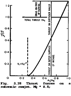
designed in such a way that it can carry the whole thrust required. To illustrate where the thrust forces act on a complete engine nacelle, we consider the simple case of a subsonic ramjet, as shown in Fig. 3.28, which is instructive because the forces can only act on the fairing (if we ignore possible drag forces on the burner elements or flameholders). For a particular set
 LIVE GRAPH
 |
Click here to view
of values of the flight Mach number, the mass-flow ratio, the heat input coefficient Cq, and hence a given total thrust Tht, the diffuser area ratio A^/Ag is varied. In this particular case, there is always a certain drag force on the rear of the fairing, acting partly as overpressures in the nozzle and partly as suction over the outer surface of the boattailed rearbody. The thrust on the intake and in the diffuser must, therefore, together sustain more than the total thrust. As the inlet area decreases, the diffuser takes more of the thrust force, thus relieving the suction over the outer surface of the intake. This example demonstrates that the main aerodynamic problems are once again reduced to the design of shapes with adverse pressure gradients along the walls, which allow the viscous layer to flow along them without causing a flow separation. A useful overall survey of ramjet performance has been given by H Gorges & J E P Dunning (1949).
Since the presence of the fairing is essential to the generation of thrust, the viscous layers along it must generate drag forces at the same time so that the effective thrust is always less than that associated with the thermodynamic flow cycle. These friction forces are unavoidable; their magnitude depends on the extent of the wetted area and on the state of the boundary layer and must be determined in each individual case. The friction forces matter more when the wetted area is large in relation to the cross-sectional area of the
engine and when the thrust per unit frontal area is small.
We have already seen that the fundamental principles of thrust generation are much the same whether the flight speed is subsonic or supersonic, but there are differences in detail. In particular, the shape of a fairing or of any other solid body to take the thrust forces depends strongly on the Mach number and, at higher Mach numbers, the body is generally designed to sustain not only thrust but also lift forces. These propulsive lifting bodies will be discussed in Section 8.6.
We have discussed the generation of propulsive forces so far mostly in terms of energy addition in the form of either heat or mechanical energy. But the most common engines in aircraft propulsion at present, installed in nacelles, are turbojets, which are mixed engines in the sense that both heat and mechanical energy are supplied (for more detailed information see e. g. J Chauvin
(1969) ). The principles of thrust generation are much the same as those discussed above. The thermal efficiency of the flow cycle of a turbojet engine shows an overall gain at subsonic and low-supersonic Mach numbers, compared with a pure heat engine, even though part of the available mechanical energy is not now used to form a jet but to drive the turbine which, in turn, drives the compressor. There are many variants of the turbojet engine. For example, in bypass or fan engines, a pure turbojet is surrounded by a second ducted air – stream, in which mechanical energy is supplied to that stream by means of a fan. This is closely related to the ducted propeller discussed above. Altogether, we can conceive of a whole spectrum of types of engine, as has been indicated in Fig. 1.1.
In many practical cases, the engine may not be installed in an isolated nacelle but in the fuselage or in or near a wing. There are then significant interference effects between engine and airframe flows, which cannot be ignored. Inlet and exit flows and jets must then be considered in their proper environments, that is to say, in the flowfields induced by the other parts of the aircraft. These problems will be discussed later in the context of the particular types of aircraft where they arise.


