Flow around slender bodies
In the foregoing part of this section it has been shown that the flow around a class of bodies of revolution can be modelled by the use of a source and sink of equal strength. Accordingly, it would be natural to speculate whether the flow around more general body shapes could be obtained by using several sources and sinks or a distribution of them along the z axis. It is indeed possible to do this as first shown by Fuhrmann.* Two examples similar to those presented by him are shown in Fig. 3.31. Although Fuhrmann’s method could model the flow around realistic-looking bodies it suffered an important defect from the design point of view. One could calculate the body of revolution corresponding to a specified distribution of sources and sinks, but a designer would wish to be able to solve the inverse problem of how to choose the variation of source strength in order to obtain the flow around a given shape. This more practical approach became possible after Munkt introduced his slender-body theory for calculating the forces on airship hulls. A brief description of this approach is given below.
Fig. 3.31 Two examples of flow around bodies of revolution generated by (a) a point source plus a linear distribution of source strength; and (b) two linear distributions of source strength. The source distributions are denoted by broken lines ♦Fuhrmann, G. (1911), Drag and pressure measurements on balloon models (in German), Z. Flugtech., 11,165. * Munk, M. M. (1924), The Aerodynamic Forces on Airship Hulls, NACA Report 184.
 |
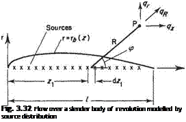
For Munk’s slender-body theory it is assumed that the radius of the body is very much smaller than its total length. The flow is modelled by a distribution of sources and sinks placed on the z axis as depicted in Fig. 3.32. In many respects this theory is analogous to the theory for calculating the two-dimensional flow around symmetric wing sections – the so-called thickness problem (see Section 4.9).
For an element of source distribution located at z = z the velocity induced at point P (r, z) is
®=^dZi <3-82)
 |
||
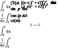
where ct-(zi) is the source strength per unit length and er(zi)dzi takes the place of Q in Eqn (3.63). Thus to obtain the velocity components in the r and z directions at P due to all the sources we resolve the velocity given by Eqn (3.82) in the two coordinate directions and integrate along the length of the body. Thus
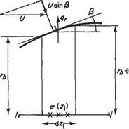
The source strength can be related to the body geometry by the following physical argument. Consider the elemental length of the body as shown in Fig. 3.33. If the body radius rj is very small compared to the length, l, then the limit r —► 0 can be considered. For this limit the flow from the sources may be considered purely radial so that the flow across the body surface of the element is entirely due to the sources within the element itself. Accordingly
2iTrqrdz = (r(zi)dzi at r = rj provided rj —► 0
But the effects of the oncoming flow must also be considered as well as the sources. The net perpendicular velocity on the body surface due to both the oncoming flow and the sources must be zero. Provided that the slope of the body contour is very
Fig. 3.33
small (i. e. dri/dz – c 1) then the perpendicular and radial velocity components may be considered the same. Thus the requirement that the net normal velocity be zero becomes (see Fig. 3.33)
qr — U sin (3 — U
dz і
![]()
 |
Oncoming flow
So that the source strength per unit length and body shape are related as follows
(3.85)
|
1 *(*i) |
where S is the frontal area of a cross-section and is given by S = 7rr|. In the limit as r —> 0 Eqn (3.84) simplifies to
Thus once the variation of source strength per unit length has been determined according to Eqn (3.85) the axial velocity can be obtained by evaluating Eqn (3.86) and hence the pressure evaluated from the Bernoulli equation.
It can be seen from the derivation of Eqn (3.86) that both r* and dr*/dz must be very small. Plainly the latter requirement would be violated in the vicinity of z = 0 if the body had a rounded nose. This is a major drawback of the method.
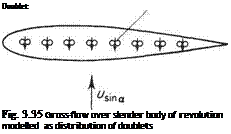
The slender-body theory was extended by Munk* to the case of a body at an angle of incidence or yaw. This case is treated as a superposition of two distinct flows as shown in Fig. 3.34. One of these is the slender body at zero angle of incidence as discussed above. The other is the slender body in a crossflow. For such a slender body the flow around a particular cross-section is closely analogous to that around a circular cylinder (see Section 3.3.9). Accordingly this flow can be modelled by a distribution of point doublets with axes aligned in the direction ♦Munk, M. M. (1934), Fluid Mechanics, Part VI, Section Q, in Aerodynamic Theory, volume 1 (ed. W. Durand), Springer, Berlin; Dover, New York.
|
l/sina
 |
Fig. 3.34 Flow at angle of yaw around a body of revolution as the superposition of two flows
of the cross-flow, as depicted in Fig. 3.35. Slender-body theory will not be taken further here. The reader is referred to Thwaites and Karamcheti for further details.*


