Forward Flight Near the Ground
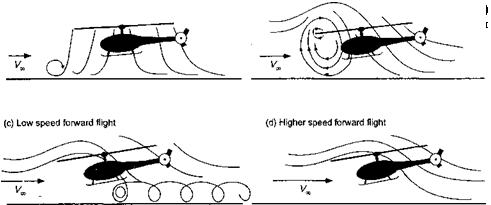
The effects of the ground on rotor performance in forward flight are also significant, but here the flow state near the rotor tends to be even more complicated. The typical behavior is shown in Fig. 5.37, which is adapted from the work of Curtiss et al. (1984, 1987). At low forward speeds, a region of flow recirculation is formed upstream of the rotor near the ground. This phenomena has negligible effects on performance but may throw loose surface material up into the air that may be reingested by the rotor. As forward speed increases, this recirculation develops into a small vortical flow region between the
ground and around the leading edge of the rotor. This vortex has been documented both in wind-tunnel experiments and helicopter operations in the field. For helicopters operating in a dusty or snowy environment the flow recirculation upstream of the rotor becomes particularly evident. This recirculation increases the inflow through the forward part of the rotor disk, and, as a consequence, the induced power requirements will increase above that
![]()
 |
required for hover IGE. The pilot, therefore, experiences a form of “p collective pitch is increased to maintain altitude as the aircraft transitions into forward flight. Above a critical advance ratio, which depends on aircraft weight (rotor thrust) and proximity to the ground, a well-defined horseshoe vortex (ground vortex) is formed under the leading edge of the rotor near the ground. With further increases in airspeed, this phenomenon disappears as the rotor wake is skewed back by the oncoming flow. Ground effect is usually considered negligible for Vqo > 2Vh or for advance ratios greater than about 0.10. See also Section 14.10.6 for a further discussion of ground effect on rotor aerodynamics.
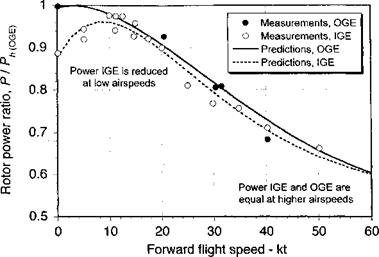
A representative set of results of rotor power in forward flight for operations in both IGE and OGE is shown in Fig. 5.38, which is reproduced from the wind-tunnel measurements of Sheridan & Weisner (1977). The advantages of ground effect are apparent for hover and very low airspeeds, where the effects indicate considerable power reductions compared to flight OGE. Note that for operation IGE the power increases rapidly as the helicopter transitions from the hover state. This is because of the formation and influence of flow recirculation at the leading edge of the rotor disk, as previously alluded to, which causes the rotor to experience a higher induced inflow than for hovering flight IGE. This increases slightly the power requirements, as previously mentioned. Similar types of results showing the same effects have been obtained by Cheeseman & Bennett (1955) on the basis of flight tests.
Similar rotor-ground plane interference effects are noted in wind tunnel tests on rotors, where the effects of the tunnel floor (as well as the ceiling and side walls, if present) can alter the induced flow through the rotor. Ganzer & Rae (1960) and Lehman & Besold (1971) have studied the effects experimentally. If the objective is to simulate free-air conditions with the rotor, then the presence of the walls on rotor performance cannot be easily discounted,
|
Figure 5.38 Measurements and predictions of rotor power versus forward speed when operating near the ground. Data source: Sheridan & Weisner (1977). |
especially at low airspeeds. For tunnel dimensions that are at least twice the diameter of the rotor, the effects of the wind tunnel walls are small for advance ratios greater than 0.1. Generally, it must always be assumed that the effects of the tunnel walls will lead to some flow recirculation at lower advance ratios (say, д < 0.1) making reliable free-air measurements of rotor performance difficult or impossible, even if suitable corrections could be derived – see also Philippe (1990). Measurement of the wall pressure signatures allows the investigator to monitor interference effects and help define the lowest allowable wind speed for a given rotor thrust and/or advance ratio that can be tested without the results being contaminated by wall interference effects. Deviations of the wall pressures from their static values will be a sensitive indicator of such interference effects, although correcting the rotor measurements is a more difficult problem. It would seem that minimizing the interference effects in the first place is the best strategy for testing helicopter rotors, which suggests the use of large wind tunnels or wind tunnels with open working sections.
Other studies of the flows associated with rotors operating IGE have used both vortex methods and grid-based computational fluid dynamic (CFD) methods. A free-vortex wake model is described by Du Walt (1966) who assumed an axisy mmetric, periodic wake. Ground effect was simulated by modeling the problem as a mirror image wake below the ground plane, and studies were conducted for varying rotor heights and advance ratios. Similar types of models have been developed by Saberi & Maisel (1987), Quackenbush & Wachspress (1989), Graber et al. (1990), Itoga et al. (1999), and Griffiths & Leishman (2002). While predictions of wake behavior in hover and in forward flight has been demonstrated, relatively limited success has been achieved in correctly predicting rotor performance IGE when compared to experimental results. This reflects the inherent complexity and strongly viscous nature of the rotor IGE flow problem. The use of most forms of CFD methods do not yet have seen to have reached the maturity for predicting rotor performance IGE, but approaches such as that discussed by Moulton et al. (2004) at least seem promising for predicting the effects of the rotor downwash at regions below the rotor, which is important for several operational reasons. The best current quantitative levels of predictive success for ground effect problems using CFD have been achieved using vorticity transport models – see Section 14.3.


