Height-Velocity (H-V) Curve
In a survey of helicopter accidents conducted by Harris et al. (2000), it was found that out of8,436 accidents, 2,408 accidents occurred because of the loss of engine power. Out of these 2,408 accidents, about half were a result of fuel exhaustion. Nine hundred thirty-five accidents resulted in substantial damage to the helicopter and 445 helicopters were completely destroyed. Besides the tragic loss of lives, such statistics are certainly not acceptable from an engineering standpoint and clearly emphasize the need for better helicopter designs with adequate single engine out performance and safe autorotational landing capability.
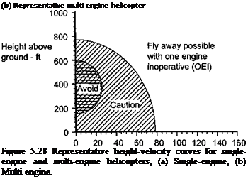
The flight conditions that will allow safe entry to an autorotation and recovery of the helicopter are summarized in the form of height-velocity or “H-V” curves. These are often called “deadman’s” curves, for obvious reasons. Figure 5.28 shows representative examples of the H-V curves for single-engine and multi-engine helicopters, which are typical of the information included in the aircraft flight manual. The curves that define the “avoid” regions are established though systematic test flights prior to certification of the helicopter. The tests are conducted at altitude relative to a virtual “floor” by incrementally approaching the
![]()
![]()
![]()
 Note: Avoid region means avoid continuous operations
Unsafe region near ground
І і і 14’Vi‘i‘r і г і І’тті і і і і і і і i-|
40 60 80 100 120 140 160
 |
Indicated airspeed – kt
Indicated airspeed – kt
combinations of airspeed and altitude where acceptable autorotational capability becomes questionable on the basis of pilot opinions, that is, a difficulty rating. The engineering results are then corrected for different helicopter gross weights and density altitudes, and charts made for the flight manual. For flight anywhere outside the avoid region the pilot should be able to safely recover the helicopter through an autorotative maneuver in the event of a flight emergency. While flight in the avoid region is not prohibited, its boundaries dictate the conditions where sustained flight operations should be avoided less there be an engine failure.
The actual size and shape of the H-V curve depends on many factors, including the characteristics of the helicopter, its gross weight, and operational density altitude [see Pegg
(1968) ]. As shown in Section 2.13.7, the disk loading Т/A is the primary factor influencing the autorotative rate of descent. The number of engines installed in the helicopter will also affect the shape of curves because flight operations (but at (reduced performance) are possible, so multiple curves may be defined for single – and multi-engine operations. Note that for a single engine helicopter there are two unsafe regions defined by the H-V curve. The avoid region at low altitude and high airspeeds determines the minimum altitude below which translational kinetic energy cannot be converted into potential energy by means of a zoom-climb prior to entering the autorotation. This boundary is also marked to prevent unsafe operations close to the ground. The most important avoid region is obviously, however, at low airspeeds.
The bottom part of the H-V curve is defined as the lowest height from which a successful autorotation can be performed from a full-power climb out, with some prescribed allowance for pilot reaction time, that is, the time between the power failure and the reduction in collective pitch. Military and civil requirements usually differ, so that the limits of the curve will also vary with the model of helicopter. The FARs require a 1-second delay, whereas the military require 2 seconds to allow for the typically higher workload of military pilots. To establish the lowest portion of the H-V diagram (zero airspeed) it is normally assumed that this is the height above which a vertical power off landing cannot be made with damaging the aircraft. Under these conditions the pilot will rapidly increase collective pitch to cushion the landing at the expense of a rapid decay in rotor rpm. The top portion of the H-V curve is established for level flight power conditions, again by including some prescribed pilot reaction time. If a power or mechanical failure occurred at this combination of altitude and low airspeed the pilot would normally dive the helicopter to gain airspeed at the expense of altitude while attempting to maintain rotor rpm with collective, followed by a flare with aft cyclic pitch as the ground is approached. Emergency descents from points near to the “avoid” region always requires a high level of piloting skill.
Reducing the size of the avoid region is obviously desirable from an operational point of view but is generally difficult from an engineering perspective. Helicopters with low disk loading will tend to have a much smaller avoid regions; hence the autorotative characteristics of the helicopter usually enter into the basic sizing and design of the rotor (see Section 6.4.1). Increasing the stored rotational kinetic energy by adding blade mass is one possibility, but this is not desirable as it will be at the expense of higher blade stresses and a lower payload. For a multi-engine helicopter the unsafe or avoid region shrinks considerably, as shown in Fig. 5.28(b). For twin-engine helicopters, the avoid region diminishes to the point where there is only a slight chance that a fly-away or safe autorotation could not be performed. For three-engine helicopters the avoid region essentially disappears in the event of a single engine failure. However, there will always be some avoid regions marked on the H-V diagram in the event of a tail rotor failure, which will require an autorotation to be performed no matter how many engines are installed.


