Incompressible Flow About an Airfoil
The physical characteristics of external flow past a thin airfoil at a small angle of attack enables us to build a simple mathematical model of the flow. We assume here our profile starts to move impulsively from the rest and reaches the constant speed of U in zero time. If the viscous forces exist, their resistance to the impulsive motion will be so large that the required force to move the airfoil will also be incredibly large. However, if we neglect the viscous effects at the beginning, the assumption of impulsive start of a motion will be more meaningful. Under this assumption, we can model the external flow in connection with the creation of lift via the bound vortex formation around the airfoil in a free stream and explain the whole phenomenon by means of Kelvin’s theorem which was introduced in Chap. 2.
3.1 Impulsive Motion
When the airfoil starts its translational motion impulsively, as observed from the body fixed coordinates, the air suddenly starts rushing towards it with the speed U and creates a velocity field V = V(x, z) parallel to the surface of the airfoil as shown in Fig. 3.1. The fluid particles move along the streamlines of the flow field. The characteristic streamline of the flow is the stagnation streamline which comes at the front stagnation point and branches into two on the surface and leaves the surface of the airfoil at the rear stagnation point. The fluid particles which move on the stagnation streamlines have naturally zero velocities at the stagnation points. There are two stagnation points for this external flow.
The fluid particles on the frontal stagnation streamline first decelerate towards the frontal stagnation point and after passing the branch point they accelerate over the upper and lower surfaces until they reach their maximum velocity. The particles moving on the upper surface move faster in a narrow passage because of the thickness of the airfoil and they slow down to zero velocity until they reach the
U. Gulfat, Fundamentals of Modern Unsteady Aerodynamics, 59
DOI: 10.1007/978-3-642-14761-6_3, © Springer-Verlag Berlin Heidelberg 2010
![]()

rear stagnation. At the lower surface, however, the accelerating flow particles move towards the trailing edge and almost circle around it and reach the rear stagnation point which for the time being is at the upper surface. The flow picture looks very unsymmetrical and the location of the stagnation points are different from the leading and trailing edges.
The velocity vector which is parallel to the surface and nonzero except at the stagnation points will be used as the edge velocity of the boundary layer which is introduced by Prandtl for analyzing the viscous effects. In the boundary layer, however, the velocity values will go to zero at the surface because of the no slip condition as shown in Fig. 3.2.
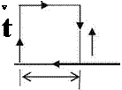
At the onset of impulsive motion very high velocity gradients take the shape shown in Fig. 3.2 in a short duration and the outside of the thin boundary layer a very large flow field remains potential. In the boundary layer the viscous effects are likely to generate a part of a circulation which contributes to the overall circulation used in generation of lift. Now, we can use our model in a boundary layer of thickness d with calculating the infinitesimal circulation dC over a rectangular boundary whose length is ds as shown in Fig. 3.3. At the left face of the rectangle, the vertical velocity is v and with increment ds its value at the right face is v + dv, and V(x, y) is the edge velocity. The infinitesimal circulation in clockwise direction becomes
dr = 0. ds + v. d + V(x, z). ds – (v + dv). d. If we neglect the second order term dv. d we find: dC = V(x, z). ds. Accordingly, the rate of increase of circulation reads as
![]()
 |
||
V (x, z) = y.
![]()
 |
||
Fig. 3.3 Local circulation dC
The boundary layer at the surface can be modeled as a vortex sheet with strength у while the outside of boundary layer is the potential flow region. This modeling represents the physics of the external flow. Let us use Kelvin’s theorem to find the total time variation of the circulation value in the flow field of the impulsively started airfoil According to Kelvin’s theorem, the total circulation remains constant throughout the motion. Since the motion starts from rest, the total circulation at the beginning is zero and remains zero to give
Г = y. ds = 0
 |
 |
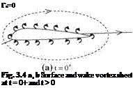
The closed integral here is evaluated around the airfoil on an arbitrary closed loop. For the sake of convenience, the closed loop can be chosen as the airfoil surface. As stated before, right after the start accelerating air particles at the bottom surface turn around the trailing edge with a very high velocity. The sharper the trailing edge, the more the speed of turning. Therefore, there is a limit to the turning speed after which the increase is not physically possible because of the pressure drop around the trailing edge. For the physically possible case, after the onset of motion the counter clockwise rotating vortex sheet of the bottom surface tries to turn around the sharp trailing edge but separates from the surface and gets carried downstream while the clockwise rotating vortex sheet of upper surface moves toward the trailing edge. The lifting force which was zero initially starts growing. In Fig. 3.4a, shown is the t = 0+ time depiction of the flow field with the upper and lower vortex sheets mentioned above. A short while after the start, the upper surface vortex sheet moves at the sharp trailing edge, and pushes
the lower surface vortex sheet down to wake until the rear stagnation point reaches the trailing edge. After this time, the flow becomes stable on the airfoil with the constant bound circulation Га as shown in Fig. 3.4b at time t > 0.
As seen in Fig. 3.4b, there are two different circulations in the flowfield. The first one is due to the bound circulation on the airfoil and the second one is due to the wake circulation. We calculate both of the circulations on clockwise paths as shown with dashed lines. The value of bound circulation can be simply found by adding the upper and lower vortex sheet strengths. The wake circulation, on the other hand, consists of only the counter clockwise rotating vortices which then add up to — Га. According to the Kelvin’s theorem, the total circulation must be zero which makes the bound circulation value Га. The picture on the upper surface remains the same, meaning that the bound circulation is present all the time moving with the airfoil to keep the rear stagnation point at the trailing edge.
At the wake, however, the counter clockwise vortices shed into the downstream, get together and form the starting vortex of strength — Га and stay at the far wake. Although it retains the same strength for a long time, its effect on the airfoil is negligible according to the Biot-Savart law since it is far away from the airfoil.
As the velocity at the trailing edge becomes zero, the vortex sheet strength of upper and lower surfaces around the trailing edge becomes equal in magnitude and opposite in sign. That means as the steady state is reached, the shed vortices into the wake cancel each other to result in no vortex sheet in near wake. Having zero velocity at the sharp trailing edge is called Kutta condition. It is the Kutta condition which generates a positive circulation and in turn creates the lifting force on the airfoil. It has been observed experimentally that 90% of the lift on the airfoil is generated with 3 chord travel of the airfoil after the impulsive start, (Kuethe and Chow 1998). The early computational fluid dynamics studies with Navier-Stokes solutions had indicated that almost all the lift is generated within the 4 chord of travel of an airfoil after the impulsive start (Gulcat 1981).
Now, we can study the steady flow thin airfoil aerodynamics by considering vortex sheet present at the surface of the profile.


