LOSS AND REVERSAL OF AILERON CONTROL-. TWO-DIMENSIONAL CASE
Ailerons control the rolling motion of an airplane. When an aileron is displaced downward, the lift over the wing increases, thus producing a rolling moment. But the aileron deflection also creates a nose-down aerodynamic pitching moment which twists the wing in a direction tending to reduce the lift and hence reducing the rolling moment. As the elastic stiffness of the wing is independent of the flight speed, whereas the aerodynamic force varies with U2, there exists a critical speed at which the aileron becomes completely ineffective. This critical speed is called the critical aileron-reversal speed. When the airspeed is higher than the critical reversal speed, the aileron control is reversed; i. e., a downward movement of the aileron on the starboard wing produces a rolling moment which moves the starboard wing tip downward. The closer the speed is to the critical speed, the less effective is the aileron control. The effectiveness of the aileron control may be expressed in terms of the rolling power of

the wing, which may be defined as the ratio of the steady rolling velocity of an airplane, due to a unit deflection of the aileron, to that of an otherwise identical airplane in the same flight condition but with an infinitely rigid wing. However, in order to simplify the problem and to obtain a convenient index for the aeroelastic characteristics of the wing itself, we shall consider the aileron control problem in a strictly static sense. We define the elastic efficiency of the aileron, or simply the aileron efficiency, as the ratio of the rolling moment produced by an aileron deflection to that produced by the same deflection on a hypothetical rigid wing of the same planform, while the wing root is rigidly held against roll. The situation may be conceived as existing in a wind-tunnel testing. The airplane
fuselage is fixed in the tunnel, while the aileron is deflected and the rolling moment measured.
Since the net rolling moment vanishes at the reversal speed, both the “rolling power” and the “elastic efficiency” become zero at the critical condition.
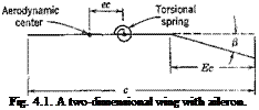
Let a be the geometrical angle of attack (measured from the zero-lift line) at a section of the main airfoil, and (j the angle of deflection of the aileron (positive downward) with respect to the main airfoil at that section (see Fig. 4.1).
 |
The lift coefficient and the coefficient of moment about the aerodynamic center can be written in the form
|
„ЗС, c, = «« + ^ |
(1) |
|
Cm = /3 -^r + OnO |
(2) |
1 ЭС /ЭС ~~i
![]()
effect of finite aspect ratio on the combination – —^ I, which
a op Op /
 |
appears in the reversal problem, is small, provided that the lift-curve slope
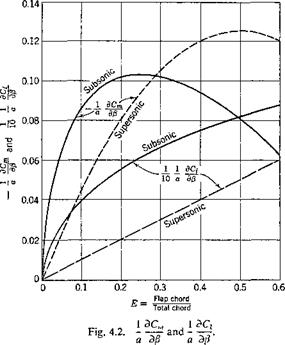
a is properly corrected for finite aspect ratio. Comparison with experimental results418 shows that the mean values of both (1/а)(ЭСг/Э/3) and at “incompressible” speeds lie at about 80 per cent of the theoretical values. The experimental values are, however, scattered and are influenced by the design details of the flap, such as its nose shape, nose gap, and aerodynamic balance.
The theoretical values of the ratios (1 /aXBCJdfi) and (1/а)(ЭСт/Э/1) are summarized in Fig. 4.2 for both the subsonic and the supersonic cases.
Let us consider a two-dimensional wing with chord length c and aileron chord length Ec, constrained by a spring to rotate about an axis at
distance ec aft of the aerodynamic center. In this case we shall say that aileron reversal occurs when the change of lift due to an aileron displacement vanishes. The lift per unit length of this airfoil is, according to Eq. 1,
Hence, at the critical reversal condition,
Now the angle of twist a of the airfoil is related to the angle of deflection of the aileron through the elastic constraint. The aerodynamic pitching moment per unit length of span about the axis of rotation is, according to Eq. 2,
M’ = q<*(eC, + P^ + cJ)
This pitching moment is balanced by the elastic restoring moment. Let К be the stiffness of the torsional restraint per unit span of the airfoil. The elastic moment induced by a rotation of the airfoil through an angle a is а К. Hence,
«К = qc2 [eCi + £“■+ Cm0j = qc2 {eav. + e$ + Q. o)
(7)
Differentiating with respect to /?, we obtain (Cm0 being a constant)
|
Эа / Эа ЭС, ЭСт кЩ-**(аЩ + ег?+-гё |
=)’ (7 a)
Substituting Эа/Э/? from Eq. 6, we obtain the critical dynamic pressure
Hence, the reversal speed is given by
which shows that the critical reversal speed increases with increasing stiffness К of the airfoil. Note that the quantity e is absent from this
formula; i. e., the position of the torsional axis does not affect the reversal speed. The reason is that the net change of lift due to aileron displacement is zero at the reversal speed.
In order to compare the loss of controlling power of an aileron due to the elastic deformation, let us define, in the two-dimensional case, the elastic efficiency of the aileron as the ratio of the lift force produced by a unit deflection of the aileron on an elastic wing to that produced by the same aileron deflection on a fictitious rigid wing of the same chord length. Now, from Eq. la, we obtain
 |
||
Hence, the rate of change of lift due to an aileron deflection is, according to Eq. 5,
On the other hand, if the wing is perfectly rigid so that К -> со, then dajdP = 0, and the rate of change of lift would be
dL’ о Э C,
dp qC dp
The elastic efficiency of the aileron is, therefore,
dL’jdp
dL’jdp
Introducing the critical-divergence dynamic pressure qdly given by Eq. 6 of § 3.1, and the critical aileron-reversal dynamic pressure qiev given by Eq. 8, we can write the above ratio as
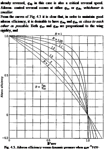
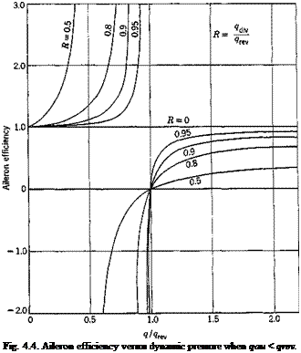
Elastic efficiency = – J—— — (10)
1 – ?/?div
When qiev < qdiv, the aileron efficiency decreases to zero when q -> qKV, as shown in Fig. 4.3, where the aileron efficiency is plotted against q/qKV, with the ratio R = qdiv/qTeY as a parameter. On the other hand, if qiev > qilv, dL’/dp -> со when q -> qdiv, as shown in Fig. 4.4; but, for qdiv < q < qlev, the aileron efficiency is negative, and the control is
 |
can be raised by increasing the rigidity. But qdlv ~ l/e, and qKy ~
![]() p Hence, the requirement qKy = qd[v implies an optimum
p Hence, the requirement qKy = qd[v implies an optimum
relation between the aileron dimensions and the wing aerodynamic center – elastic-axis eccentricity. In the two-dimensional incompressible case, an optimum aileron chord ratio as a function of the eccentricity e is given by the condition
![]()
![]() ffrev
ffrev
9div
and Glauert’s formulas (Eqs. 3 and 4); i. e.,
![]() (1 – E)VE( 1 – E)
(1 – E)VE( 1 – E)
arc cos (1 – 2E) + 2/£(l – E)
 |
For example, if the elastic axis is located at 40 per cent chord behind the leading edge, the optimum aileron chord ratio is 31 per cent.


