MAXIMUM LIFT DURING LANDING
Besides stability and control, the primary requirement for landing is high lift to reduce the speed at touchdown. This, of course, is accomplished by increasing the maximum lift coefficient of the airplane. In fact, trailing-edge wing flaps were invented and developed as “landing flaps”.
Landing Characteristics. The lifting system needed to give the best landing performance is chosen in a manner similar to that used to find the best configuration for takeoff. For landing, however, the highest CLx possible is of importance as this reduces the speed at touchdown and makes possible a shorter landing roll. Since the glide slope is proportional to the drag lift ratio, high drag during


 landing is desirable as it makes possible a steep approach angle. Practical flying qualities limit the approach angle, however, especially with the larger high speed and high performance aircraft. As the speed is reduced the approach angle can be higher as long as adequate control power is available.
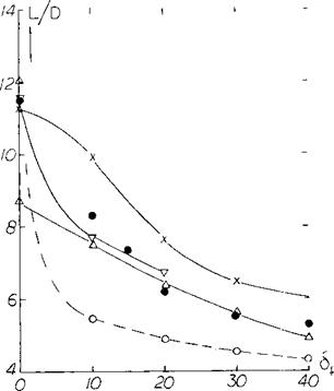
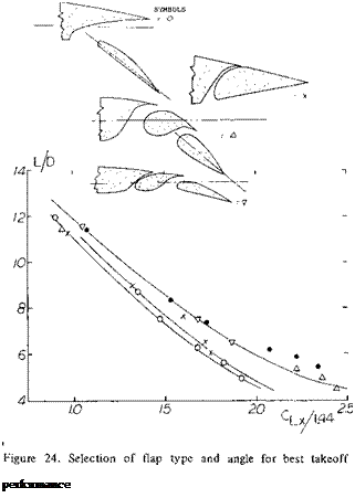
Although high drag may be desirable along with high levels of during landing, it may be necessary to abort the landing in which case the lift drag ratio again must be high. For the aborted landing condition the problems of flap and wing designs are like the takeoff condition. That is, a certain minimum L/D is necessary to provide the rate of climb required see figure 24. In this case, however, the L/D needed is lower as the airplane is usually operating at a lower weight for landing and full power is generally allowed for this condition (19,b).
Full-Span Flaps. The maximum lift will, of course, be obtained with full-span flaps, provided that lateral (and other) control would still be sufficient. The maximum coefficient then depends upon the type of flap, its angle of deflection, the shape of the airfoil, forebody and the Reynolds number as discussed in Chapter IV. However, variation and combination of these parameters leads to hundreds of possibly “optimum” configurations. In order to hold down the number, we will consider the more practical shapes and we will correlate the maximum lift coefficients versus simple parameters such as the airfoil and thickness ratio. As far as the flow pattern at CLx is concerned, it may be correct to say that all types of flaps when used at larger angles of deflection exhibit separation. To say it in different words, the flap stalls first; lift may then continue to rise with the angle of attack; and the final stall may be expected to take place from somewhere along the upper surface of the airfoil and possibly at the leading edge of the airfoil. This is the reason for the development of leading edge devices for the prevention of separation as discussed in the next chapter.
(23) Experimental investigation of partial-span wing flaps:
a) Wenzinger, Split Flaps, NACA TRpt 611 (1937).
b) Silverstein-Katzoff-Hootman, Comparative Tunnel and Flight Investigation of Maximum Lift, NACA TRpt 618
(1937) .
c) House, Slotted Flaps on 23012 Wings, NACA TN 719 (1939); continuation of TN 472 (split flaps), TN 505 and TN 663 (split flaps) 1938.
d) Neely, Tapered Wing With Fowler Flaps, NACA WRpt L-134 (1946).
e) Johnson, Flaps on Straight Wing, NACA TN 2080 (1950).
f) Schneiter, Plain-Flap Ailerons, NACA TN 1738 (1948).
g) Sherman, 18 Wing-Fuselage Combinations, NACA TN
(1938) .


