PITCH STIFFNESS AND POSSIBLE CONFIGURATIONS FOR FLIGHT
In Fig. 6.1 we have shown that the pitching moment M is zero, which is, of course, one of the conditions for equilibrium. It is intuitively evident, without recourse to any formal stability theory, that there might be something wrong with a flight vehicle that at constant speed and with fixed controls, experienced a positive (nose-up) pitching moment ACm following an increase Да in the angle of attack from its equilibrium value. This is illustrated in curve a of Fig. 6.3 (i. e. Cmx > 0). For then the moment AC’TO
|
Fig. 6.3 Pitch stiffness. |
would be such as to increase further the perturbation in a. On the other hand, if the Cm vs a relation is as in curve b, {Oma < 0) the moment following the disturbance is negative, and tends to restore a to its equilibrium value. The latter case is exactly parallel to that of a mass on a spring, which when disturbed from equilibrium, experiences a restoring force. The vehicle possesses as it were an “aerodynamic torsion spring” that tries to hold а constant at its equilibrium value. This property has traditionally been called “static stability” in pitch. In view of the more formal, more precise meaning now usually attached to the word stability (see Chapter 3), a more appropriate designation is positive pitch stiffness. The complete stability theory of the longitudinal motion (see Chapter 9) shows that positive pitch stiffness (Gm < 0) is in general neither necessary nor sufficient for stability. However, it is nevertheless a very important practical design criterion, the violation of which leads to consequences that can rarely be tolerated. The great importance of pitch stiffness makes calculation or measurement of Cm(a) one of the central features of the aerodynamic design of all flight vehicles. This curve is typically monotonic in a over the usable flight range, as in Fig. 6.3, curve b.
We may conclude then, that a satisfactory flight configuration must not only have Gm = 0 at some a > 0 in order to trim (i. e. be in pitch equilibrium) at positive lift, but at the same time must usually have Gm < 0. Alternatively, as can be seen from Fig. 6.3, it must have (7TOo > 0 and (7 < 0. It is
somewhat simpler to use the latter form of the criterion to assess the possibilities for flight.
We state here without proof (this is given in Sec. 6.3) that dCmlda can be made negative for virtually any combination of lifting surfaces and bodies by placing the center of gravity far enough forward. Thus it is not the stiffness requirement, taken by itself, that restricts the possible configurations, but rather that it must coexist with zero moment. Since a proper choice of the C. G. location can ensure a negative ЭС^/Зк, then any configuration with a positive Cmo can satisfy the conditions for flight at L > 0.
Figure 6.4 shows the Cma of conventional airfoil sections. If an airplane were
|
Positive camber Zero camber Negative camber Cm„ negative Cm0 = 0 cm0 positive Fig. 6.4 Cmo of airfoil sections. |
to consist of a straight wing alone (flying wing), then the wing camber would determine the airplane characteristics as follows:
Negative camber—flight possible at a > 0; i. e. CL > 0.
Zero camber—flight possible only at a = 0, or CL = 0.
Positive camber—flight not possible at any positive a or 0L.
For straight-winged tailless airplanes, only the negative camber satisfies the conditions for flight. Effectively the same result is attained if a flap, deflected upward, is incorporated at the trailing edge of a symmetrical airfoil. A conventional low-speed airplane, with essentially straight wings and positive camber, could fly upside down without a tail, provided the C. G. were far enough forward. The positively cambered straight wing can be used only in conjunction with an auxiliary device which provides the positive Cmo. The solution adopted by experimenters as far back as Samuel Henson (1842) and John Stringfellow (1848) was to add a tail behind the wing. The Wright brothers (1903) used a tail ahead of the wing (Canard configuration). Either of these alternatives can supply a positive Cmo as illustrated in Fig. 6.5. When the wing is at zero lift, the auxiliary surface must provide a nose-up
 |
Tail with + Cambered wing at
CL positive CL = 0
(b)
Fig. 6.5 Wing-tail arrangements with positive (7mo. (a) Conventional arrangement. (6) Tail-first or Canard arrangement.
moment. The conventional tail must therefore be at a negative angle of attack, and the Canard tail at a positive angle.
 |
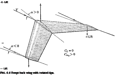
An alternative to the wing-tail combination is the swept-back wing with twisted tips (Fig. 6.6). When the net lift is zero, the forward part of the wing has positive lift, and the rear part negative. The result is a positive couple, as desired.
A variant of the swept-back wing is the delta wing. The positive Gm<) can be achieved with such planforms by twisting the tips, by employing negative camber, or by incorporating an upturned tailing edge flap.


