SUPERPOSITION OF DOUBLET AND FREE SYSTEM: FLOW AROUND A CYLINDER
 |
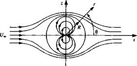
Consider the superposition of the free stream potential of Eq. (3.51), where x = r cos 0 in cylindrical coordinates, with the potential of a doublet (Eq. (3.68)) pointing in the negative x direction [ц = (~ц, 0)]. The combined flow, as shown in Fig. 3.11, has the velocity potential
1 ЗФ / U
<395)
If this flow combination is thought of as a limiting case of the flow in Section 3.10 with the source and sink approaching each other, it is expected that the oval will approach a circle in this limit. To verify this, note that qr = 0 for r = У/р/2лик for all 0 (from Eq. (3.94)) and the radial direction is normal to the circle. If we take r = R as the radius of the circle, then the strength of the doublet is
ft = UJ2nR2 (3.96)
Substituting this value of fi into Eqs. (3.93), (3.94), and (3.95) results in the flowfield around a cylinder with a radius R:
|
/ R2 Ф = U„ cos 0^r H—————- J |
(3.97) |
|
/ R2 qr = U„ cos 0^1 — – jjj |
(3.98) |
|
/ r2 qe = – U„sin e[l + ^jj |
(3.99) |
For the two-dimensional case, evaluation of the stream function can readily provide the streamlines in the flow (by setting 4* = const.). These results for the cylinder in a free stream can be obtained, too, by the superposition of the free stream and the doublet [with (-/i, 0) strength] stream functions:
4» = f/„rsin(9-^-— (3.100)
2я t
The stagnation points on the circle are found by letting qe = 0 in Eq. (3.99), and are at 0 = 0 and 0 = л. The value of V at the stagnation points 0 = 0 and 6 = л (and therefore along the stagnation streamline) is found from Eq. (3.100) to be V = 0. This is equivalent to requiring that qr(R, 0) = 0, and the strength of Ц again is given by Eq. (3.96). Substituting ц in terms of the cylinder radius into Eq. (3.100) yields
4> = U„sine(r-!yJ (3.101)
This describes the streamlines of the flow around the cylinder with radius R (Fig. 3.12). These lines are perpendicular to the potential lines of Eq. (3.97).
To obtain the pressure distribution over the cylinder, the velocity components are evaluated at r = R:
![]() qr = 0 qe = —21/„ sin 0
qr = 0 qe = —21/„ sin 0
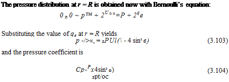 |
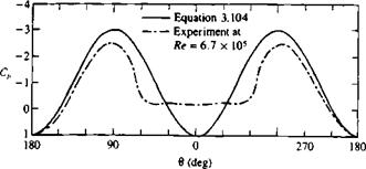
It can be easily observed that at the stagnation points 0 = 0 and л (where q = 0) Cp = 1. Also the maximum speed occurs at the top and bottom of the cylinder (0 = л/2, Зл/2) and the pressure coefficient there is —3.
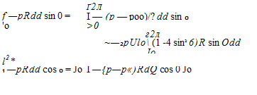
To evaluate the components of the fluid dynamic force acting on the cylinder, the above pressure distribution must be integrated. Let L be the lift per unit width acting in the z direction and D the drag per unit width acting in the x direction. Integrating the components of the pressure force on an element of length R dd leads to
![]()

 |
 |
(3.105)
(3.106)
Here the pressure was replaced by the pressure difference p – term of Eq. (3.103), and this has no effect on the results since the integral of a constant pressure around a closed body is zero. A very interesting result of this potential flow is that the fore and aft symmetry leads to pressure loads that
|
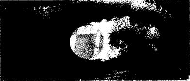
FIGURE 3.13 Hydrogen bubble visualization of the separated water flow around a cylinder at a Reynolds number of 0.2 x 10⁶ (Courtesy of K. W. McAlister and L. W. Carr, U. S. Army Aeroflightdynam – ics Directorate, AVSCOM). |
cancel out. In reality the flow separates, and will not follow the cylinder’s rear surface, as shown in Fig. 3.13. The pressure distribution due to this real flow, along with the results of Eq. (3.104), are plotted in Fig. 3.14. This shows that at the front section of the cylinder, where the flow is attached, the pressures are well predicted by this model. However, behind the cylinder, because of the flow separation, the pressure distribution is different.
In this example, because of the symmetry in the upper and the lower flows (about the x axis), no lift was generated. A lifting condition can be obtained by introducing an asymmetry, in the form of a clockwise vortex with strength Г situated at the origin. The velocity potential for this case is
Ф = f/,0 cos в^г + — ~~ 0 (3.107)
|
FIGURE 3.14 Theoretical pressure distribution (solid curve) around a cylinder compared with experimental data at Reynolds number of 6.7 x 10s (chain curve) from Ref 1.6. |
The velocity components are obtained by differentiating the velocity potential
which is the same as for the cylinder without the circulation, and
![]()
![]()
![]() (3.109)
(3.109)
This potential still describes the flow around a cylinder since at r = R the radial velocity component becomes zero. The stagnation points can be obtained by finding the tangential velocity component at r = R,
These stagnation points (located at an angular position 8S) are shown by the two dots in Fig. 3.15 and lie on the cylinder as long as Г < 4nRU„.
The lift and drag will be found by using Bernoulli’s equation, but because of the fore and aft symmetry no drag is expected from this calculation. For the lift, the tangential velocity component is substituted into the Bernoulli equation and
L = J -(p – p^)R d6 sin в = – J^ [^^_2 (2^«=sin в + j sin 8Rdd
= f sin2 8dd = pUJ (3.112)
Л Jo
This very important result states that the force in this two-dimensional flow is directly proportional to the circulation and acts normal to the free stream. A generalization of this result was discovered independently by the German mathematician M. W. Kutta in 1902 and by the Russian physicist N. E. Joukowski in 1906. They observed that the lift per unit span on a lifting airfoil or cylinder is proportional to the circulation, consequently the Kutta-
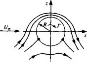 FIGURE 3.15
Streamlines for the flow around a cylinder with circulation Г.
Notation used for the generalized Kutta – Joukowski theorem.

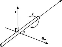 Joukowski theorem (which will be derived in Chapter 6) states:
The resultant aerodynamic force in an incompressible, inviscid, irrotational flow in an unbounded fluid is of magnitude pQ_Г per unit width, and acts in a direction normal to the free stream. (Note that the speed of the free stream is taken to be since the stream may not be parallel to the x axis.)
Using vector notation, this can be expressed as
![]() F = pQoo X Г
F = pQoo X Г
where F is the aerodynamic force per unit width and acts in the direction determined by the vector product, as shown schematically in Fig. 3.16. Note that positive Г is defined according to the right-hand rule.


