Wake Model
 |
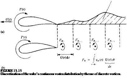
As was discussed in Sections 4.7 or 13.3, the wake shed from the trailing edges of lifting surfaces can be modeled by doublet or vortex distributions. In the two-dimensional case the unsteady airfoil’s wake will be shed only if the airfoil’s circulation varies with time (Kelvin’s condition). Therefore, if the airfoil circulation is varying continuously, then a continuous vortex sheet will be shed at the trailing edge, as shown in Fig. 13.15a. For simplicity, a discrete vortex model of this continuous vortex sheet is approximated here, as shown in
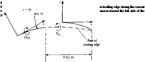
Fig. 13.15ft. The strength of each vortex IV is equal to the vorticity shed during the corresponding time step At such that Г^ = yw(t)U(t) dt. Consequently, for each vortex element, its strength and location must be specified. In regard to specifying wake-vortex location, consider the first wake element after the beginning of the motion, as shown in Fig. 13.16. The wake was “probably” shed at the airfoil’s trailing edge, which moved during the latest time step along the dashed line. (Note, again, that in this figure the fluid is stationary and the airfoil moves to the left!). So at first estimate it will be placed on this line. The distance and relative angle to the trailing edge are important numerical parameters, and usually the wake vortex location should be aligned with the trailing edge and be placed closer to the latest position of the trailing edge. (This is so, since the discrete vortex when placed at the middle of this interval is an approximation that underestimates the induced velocity when compared with the continuous wake vortex sheet result. This is mainly due to the small distance (zero distance) of the continuous wake from the trailing edge during the time interval, compared to the relatively larger distance of an equivalent discrete vortex with similar vorticity placed amid the interval of the latest time step. A typical numerical approach to correct for this wake-discretization error is to place the latest vortex closer to the trailing edge (e. g., within the range of 0.2-0.317(f) At as shown schematically in Fig. 13.16).
The strength of the latest vortex element is calculated by using Kelvin’s condition (Eq. (13.6)), which states that
![]()
 |
dr dT(t) | dTw dt dt dt
where T(f) is the airfoil’s circulation and is the wake’s circulation,
respectively. For the first time step
Г(0 + = 0
and for the ith time step
= (13.52a)
or by assuming that the Kelvin condition was met at the previous time step then
L-[r((,)+ELt] (13.52*)
It must be noted, too, that the Helmholtz theorems of Section 2.9 imply that there is no vortex decay. That is, if a wake vortex element is shed from the trailing edge its strength will be conserved (which is a good practical approximation for most high Reynolds number flows).
Since the vortex wake is force-free, each vortex must move with the local stream velocity (Eq. (13.21a)). The local velocity is a result of the velocity components induced by the wake and airfoil (wing), and is usually measured in the inertial frame of reference X, Z. To achieve the vortex wake rollup, at each time step the induced velocity (и, w), is calculated and then the vortex elements are moved by
(Ддг, Az), = (и, w), At (13.53)
In this simple scheme the velocity components and vortex positions of the current time step are used. But more refined techniques can be applied here that may improve the wake shape near the trailing edge (by using information from the current and previous time steps).


