AEROFOIL SECTIONS AND LIFT COEFFICIENTS
The efficiency of a wing is influenced greatly by its aerofoil section or profile, which has some degree and type of camber and some thickness form (Fig. 2. Id). Fuselages and other similar-shaped components of a model also produce some lift force, depending again on their shape and angle of attack. Re-entry vehicles for space flight have been designed as ‘lifting bodies’ without wings, but for almost all practical purposes in aeromodelling, the lift contribution of fuselages may be ignored. However, a fuselage does produce forces analogous to lift which affect the stability of the model, almost invariably in ways that oppose the efforts of the stabiliser to hold the mainplane at a fixed angle of attack. Similar lateral unstabilising forces are resisted by fins, which are small wings set at right angles to the mainplane, producing sideways ‘lift’ to correct yaw and sideslipping.
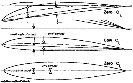
For convenience, aerodynamicists adopt a convention which allows all the very complex factors of wing trim and shape to be summed up in one figure, the coefficient of lift. This tells how the model as a whole, or any part of it taken separately, is working as a lift producer. A lift coefficient or Cl of 1 -3 indicates more lifting effect than Cl = 1.0 or 0.6, while Cl — 0.0 indicates no lifting effect at all. Cl has no dimensions since it is an abstract figure for comparison purposes and calculations.
For level flight, the total lift force generated by a model must equal the total weight, so it is possible to write:
Total Lift = Total Weight, or L = W (Action = Reaction).
This will not apply exactly if the model is descending or climbing. The exact relationships between lift and weight for these conditions are given in Fig. 1.4. As Figure 2.1. shows, the factors affecting lift force are model size or area, speed of flight, air mass density and the aerofoil-plus-trim factor, Cl – In every case, an increase in one of these factors, greater
Fig 2.1 Contd.
 |
0 Lifting effect or lift coefficient CL
area, more speed, increased density or higher lift coefficient, will produce a larger lift force. It is to be expected that when a formula for lift is worked out, it will include all these factors. In mathematical language,
Lift = some function of p, V, S, and Cl
The standard, formula, which arises out of the basic principles of mechanics and the pioneer work of Daniel Bernoulli in the eighteenth century, is
L=HxpxV2xSxCL
It is not particulary important for modellers to know this formula but it is necessary to see how the various factors iii the lift equation are interdependent For a model to be capable of level flight the lift must equal the weight If the model’s weight increases (as when it turns out heavier than expected), a larger lift force will be needed to support it Some item on the right hand side of the equation, or more than one of them, must be increased. The
modeller has no control of air density, p. The model could be re-trimmed, increasing the wing’s angle of attack to get a higher Cl – More wing area might be added, although this would add mass and increase the speed of flight. Since V is squared in the formula (multiplied by itself), a relatively small increase in V yields a large increase in lift force, other things being equal. It follows from this that a heavy model (of given area, trim, etc.) has to fly faster than a light one. However, to increase V takes energy and in an extreme case the engine of the model may be incapable of giving sufficient power to sustain flight. In such a case, if launched from a height the model would descend at some angle like a glider, even with engine at full power.


