Application Test Cases
1.1.1 The RAE 2822 Profile
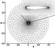
As a first application test case for the method of iterated defect correction we simulated the flow around the RAE 2822 profile in two dimensions. It is one of the official test cases of the project MUNA. We solve only the nonlinear Euler equations for this test case, so the grid we used is fully unstructured and contains about
18.0 elements with a relatively high discretized profile of 180 points per each half of the profile. The farfield is situated at 40 cord lengths and the profile is simulated as slip wall with the velocity normal to the wall set to zero. The flow was defined by the flow conditions of the so-called test case 9 with Ma = 0.73 and an incident angle a = 2.78°. This yields a transonic flow with a shock on the upper side of the profile (see Fig. 6, right). To compare the solution of the iterated defect correction we performed the simulation on the same grid with the numerical code of the DLR
 |
 |
Fig. 6 Fully unstructured grid for the RAE 2822 profile (left) and Mach number distribution of the corrected solution and a direct solution with the TAU code using a second order TVD upwind scheme (right)
("Deutsches Zentrum fur Luft – und Raumfahrt"), the TAU code, used as standard code for the project MUNA. The parameters for the TAU code were set to a second order TVD scheme with a least squares reconstruction and the Roe approximation for the convective flux.
In the case of iterated defect correction we used a first order basic method and corrected the steady solution by a local defect reconstructed with the WENO method described in section 3 using polynomials of degree two. The difference between the basic method and the corrected solution can be seen for the aerodynamic coefficients. In Fig. 7 we show the lift and drag coefficients over the number of iterations. Our iterative method is a rather suboptimal explicit method and so the number of iterations needed for a steady solution is quite high but does not influence the defect correction and is not of interest here. When the solution does not change any more we compute the local defect and solve afterwards the modified equations (5) to obtain a corrected solution which is denoted by the small arrows in Fig. 7. So each small arrow stands for a defect correction iteration.
We can see that the lift coefficient could already be corrected to the end solution after just one defect correction, whereas the drag coefficient needs some more defect correction iterations to converge. In the case of the lift coefficient a correction of about 11% was obtained and the drag coefficient could be corrected with even 28% of the first order solution, what corresponds to a total reduction of around 80 drag counts. The results of the TAU code serve here not only for validation but as a comparison as well, not having an exact solution for this test case.
In addition to the aerodynamic coefficients we can clearly see that by the iterated defect correction method with a 3rd order WENO reconstruction the shock is better resolved than it is with the second order least squares in the TAU code (see Fig. 6, right). Only if we once adapt the grid globally we are able to reach approximately the same shock resolution with the second order scheme.


