Blade Element Theories
The simple momentum theory provides useful information regarding the action of a propeller but none for its detailed design. We usually resort to a blade element approach. The forces acting on a differential element of the blade are determined and then integrated over the radius in order to predict the thrust and torque characteristics of the propeller.
|
|
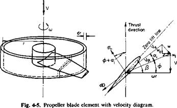
A differential blade element of chord c and width dr, located at a radius r from the propeller axis, is shown in Fig. 4-5. The element is shown acting under the influence of cor, the linear velocity V, and vv. The three velocities add vectorially to produce a resultant velocity, Ve. The section has a geometric pitch angle of its zero lift line of [i. If we assume that V and cor are known, the problem is that of calculating w, because if tv is known a, can be calculated, hence the section angle of attack a. Knowing a, we can calculate C, and Cd> whence the differential lift and drag of the section follow. However, w depends on dL which in turn depends on w. Thus the problem is closely related to the finite wing problem but is more complicated because of the helicoidal geometry of the propeller.
Combined Momentum—Blade Element Theory A first approximation to w can be obtained by applying the previously developed momentum principles to an annulus of width dr and radius r. In addition, the angle <xt, as well as e, the drag-to-lift ratio of the section, is
assumed to be small, w, also, is assumed to vary only with the radius. With these assumptions, the thrust can be obtained from momentum principles as
dT = p(2nr drV + a, FK cos ф)2аіУя cos ф;
but for a propeller with В blades dT is also given by
dT = BjpVRca0(fS — ф — a,) cos ф dr.
By equating these two expressions we obtain
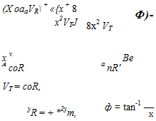
 (4-19)
where
The induced angle of attack a, can be obtained from (4-19) as
If we are given the propeller geometry /? and c and the ratio of the forward velocity to the tip speed A, the induced angle of attack can be calculated from (4-20). Knowing this, we determine the angle of attack (P — ф — otj) from which C, and Cd are obtained. The thrust and power can then be predicted by
![]()
 VRcCt cos ф( 1 — є tan ф) dr,
 |
|
a>rV2RcCl cos ф(е + tan ф) dr,
 |
When CT and CP are multiplied by a2 and A3, respectively, these products are finite for A = 0. Note that
A parameter sometimes of interest in the analysis of a propeller is the average lift coefficient. Suppose in (4-21) that о and C, are independent of x. This equation can then be written as
KT = <rC, f x-sjl2 + x2 dx (for 6i0)
so that
![]() ЪКТ
ЪКТ
<т[(1 + A2)3/2 – A3]
The combined blade element momentum theory does not account for the loss of lift toward the tips of the blades. As in the finite wing, the lift on the propeller blades must go to zero at the tips. The vortex theory to be developed next does consider this boundary condition. However, for the combined blade element momentum theory the concept of an effective radius is used to account approximately for the loss of thrust toward the blade tips. It is assumed that the thrust acts only out to a radius of BR, so that Eq. (4-21) becomes
Equation (4-22) for the power becomes KP = xa(X2 + x2)C, cos ф(е + tan ф) dx
Jo
![]() -I – x<t(A2 + x2)Cdo cos ф dx,
-I – x<t(A2 + x2)Cdo cos ф dx,
Jb
where Cdo = Cd for C, = 0.
There are numerous rules and guides for the calculation of the effective dimensionless radius B. The use of В is, of course, an approximation, for the thrust must drop off continuously to zero at the tip. The value of В that most closely approximates the actual case would depend on the section cC, distribution of the propeller. Thus it is difficult to give a hard and fast rule
for its determination. Instead, it is recommended that a value of В = 0.97 be used for preliminary estimates.


