Boundary-Layer Control by Blowing
Blowing over trailing edge flaps and the “jet flap” are presented in Chapter V. Blowing can also be used at, or near, or around the leading edge of an airfoil, to prevent or postpone stalling (separation) at higher angles of attack.
“Round” Airfoil Boundary-layer control was applied to a round-nosed and cambered section (28,b). As shown in figure 37, blowing is most effective from around x = 0.4c, as far as the magnitude of maximum lift is concerned. The experiments appear indicate that
&CL 4 s/c -/c7;
Roughly, it may also be said that
— v Cp~C<s ;
where Cp ~ Cq. The downstream-directed slot as in figure 37, was also used to try BL suction. In comparison,
this type of control reaches a certain limit (after removing the boundary layer). By contrast, blowing downstream, not only restores full energy; as shown in the graph, for CpCq – 0.12, it can also add momentum to the flow reaching to and beyond the trailing edge in a manner similar to that of a jet flap.
A Comparison of blowing and suction through two slots, is reported in (28,a). When discharging through forward slot, stalling of the RAF-31 section is comparatively gentle, between оі = 14 and 19° , for A = 6; maximum lift is increased from CLX = 0.9 to 1.6. By comparison, when sucking (through rear slot) the drop in CL is comparatively sharp, while the maximum lift obtained is only modest (CLX = 1.2). The result of suction is better, however, when using the forward slot (CL* = 1.4). Blowing is thus found to be superior as to lift as well as in regard to the quality of stalling. The low Reynolds number of this experimental investigation (Rc = 2(10) ) should be noted, however.
 |
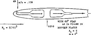
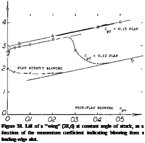 Combined Blowing. The type of stall (“abrupt.” or “gentle”) is qualitatively indicated in figure 37. When blowing from near the leading edge, the loss of lift is likely to be abrupt. Stalling can be made more gentle in this case, by increased flow. Another way of improving the quality of stall, would be blowing from farther forward. This is done in the configuration as in figure 38, where blowing from the leading edge is combined with that over a 60° trail – ing-edge flap. For a given discharge at the flap, lift at constant angle of attack of a “wing” with = 5, increases along a straight line, as the momentum coefficient for the nose slot is increased. This increment represents increased circulation. It does not stem, however, from any improvement of the flow over the trailing flap. In fact, that flap stalls beyond a certain increment of lift, as the momentum coefficient of the flap discharge is no longer sufficient to keep the flow attached.
|
round numbers: |
|||
|
<** |
= |
zero |
angle of attack in 2-dimensional flow |
|
= |
60 |
blowing trailing-edge flap, with C^ = |
|
|
CL |
= |
3.0 |
maximum lift coefficient |
|
s/c |
= |
0.2% |
slot-width ratio, indicating outlet area |
|
w/v |
= |
5 |
the blowing velocity ratio |
|
Cq0 |
= |
0.01 |
volume-flow coefficient of blowing |
|
Cpo |
= |
25 |
blowing pressure coefficient = A p/q |
|
C-uo |
= |
0.1 |
nose-slot momentum coefficient |
|
x/c |
= |
0.7 |
indicating distance between slots |
The procedure illustrated is as follows:
a) The loss of momentum between nose and flap corresponds to the BL thickness
а/с = (x/c)(U/vf 0.5 Cf ж 0.005 (27)
where U = average potential velocity along the upper side of the airfoil, assumed to be = 2 V; and Cf = 0.003.
b) The momentum discharged, has to be at least as great as the loss under (a):
CM = (1,5/a/c + (Us /V) h(slc) f ~ 0.08 (28)
where U = potential velocity at the location of the slot, assumed to be = 3V.
In all these equations and values (25) compressibility has not been taken into account. Considering velocity ratios up to 5, and/or Cp = 25, a more accurate calculation as in (28,c, d) may be advisable. – For the airfoil in figure 38, the minimum moment coefficient computed above, is shown at the left edge of the graph.
Ground Proximity. The configuration as in figure 38, was also tested (28 ,e) at higher Reynolds numbers (see figure 39) and in ground effect. A reduction of circulation is found near the ground, similar to that as shown in Chapter V for example from CL = 7, down to half, at h = 0.4c. So, there is no incentive for designing high-lift airplanes in low-wing form. Assuming, h = c to be a realistic height in a conventional airplane, the reduction is still from CL = 7, for example, almost down to 5. The reduction is negligible, however, for a wing with CL = 4.
Stalling. Blowing over the 60° flap of the configuration in figure 39 is so effective that a lift coefficient of almost CLX = 8 is obtained (30). Stalling takes place abruptly, however, within an interval of 1 or 2°, so that the use of such a wing would not be practical (would be dangerous). Separation (from the leading edge) could be prevented by means of a slat (or a nose flap). In the investigation quoted, blowing out of a slot located near the leading edge was used, however. With the help of this slot (and an
(28) High lift through blowing along the upper side of airfoils:
a) Perring (RAE), Withdrawing and Discharging, ARC RM 1100 (1927).
b) NACA: Knight TN 323 (1929) and Bamber Rpt 385 (1931); Blowing and Suction Through Backward-Opening Slot.
c) Thomas, a) Increasing Lift Through Flap Blowing, b) Calculation of Momentum Required, ZFW 1962 p 46.
d) Gersten, From Nose and Over Flap. Rpt DFL-189 (1962).
e) Lohr, Braunschweig Rpts DFL-0116 & -0188 (1961/63); also DLR-1964-02.
appreciable value of the momentum coefficient) a very gentle stall is obtained. This characteristic improves further when approaching the ground. Optimum conditions for the NACA 0010 airfoil configuration tested, including maximum lift, are then found when discharging half of a given value of momentum over the 60 flap, and the other half from the leading edge. An angle-of-attack range of 20 is thus obtained where the lift coefficient remains within plus/minus 5% of CL =5, for example. Of course, at lift coefficients of such magnitude, appreciable interference can be expected from the plates between which the airfoil was tested.

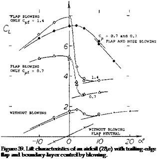 Pitching Moments. As reported in (28,e) blowing from the leading edge produces less negative (that is, more desirable) moments than when using trailing flaps producing the same lift increment. For example, at CL = 4, using a total Qu. = 0.7, the coefficient of the configuration as in figure 39, is in the order of:
ОиД = — 0.6 when blowing over the flap = – 0.3 blowing 1/2 nose and 1/2 flap
However, the differential reduces when approaching maximum lift. At and beyond Cux, all pitching moments presented in (28,e) turn strongly negative. This tendency not confirmed in other references would make an airplane very stable, and stalling impossible. Regarding the configuration in figure 39, it must also be said that it is not “balanced”. The angle of attack for CLX is around zero. The flap is too “strong”. A smaller flap, a lower angle of deflection, or increased blowing from the nose flap at the leading edge would give a more desirable attitude at modestly positive angles of attack.
|
L* |
![]()
Blowing From the Knee of nose flaps is reported in several references. In (27,a) CLX is increased from 1.5 to CLX =
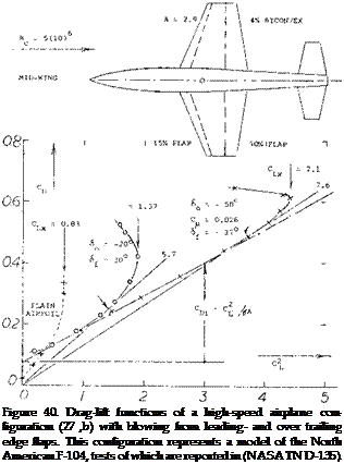
3.0, for a plain trailing-edge flap deflection of 30°, using a round-nose-flap angle 6© between – 5 and – 25°, for Cqo = 0.007. For the airplane configuration as in figure 40, the following lift coefficients were obtained:
0.83 for the plain airfoil section
1.47 with 37° trailing, and – 30° nose flap
1.92 with ($4. – 37*, Qu. i = 0.016; and – 40° nose flap
2.10 with <f* = 37° ;Ou.*= 0.016; <f0 = -50° ; C*© = 0.010
In comparison to the very high moment coefficients with C^x. above unity as in figure 39 producing CL higher than 7, the coefficients used or obtained in this configuration are modest; the combined Gu – is 0.026, and the highest
CLK is 2.2. The larger lift increment comes from blowing over the trailing flaps. Deflection of, and blowing over the knees of the nose flaps makes these more effective, however, so that they can be deflected up to — 50 . — Other advantages are:
a) While bf = 47° produces somewhat higher lift, the quality of stalling is better (more gentle) for 64 = 37®.
b) While 2/3 span flaps provide about the same lift as full-span flaps, stalling is more gentle in the latter condition.
c) No hysteris was found in the CL (a ) function when using blowing flaps as indicated.
d) For landing, “boundary-layer control results in a considerably reduced speed and reduced distance”.
e) When blowing over the ailerons (which are portions of the flaps) they were “very effective lateral control devices”.
Tests on an actual North-American F-104 in a full scale tunnel using the same wing as in figure 40 with the same flaps, but with the ailerons neutral and a wider fuselage show only a CLX =1.57.
Takeoff. In order to get some insight into performance, the characteristics of the airplane as in figure 40, are plotted in polar form. Takeoff (see analyses in (27,b, c)) is a more difficult operation than landing as engine power is limited. Not only high lift, but also drag and BL control power have to be considered. Besides the plain wing, the illustration shows two selected high-lift configurations, not necessarily optimum in performance, but with comparatively gentle stalling characteristics:
|
performance parameter |
plain |
without |
with BLC |
with “drag’ |
|
Cl* |
– 0.83 |
– 1.37 |
– 2.10 |
– 2.10 |
|
(L/D), |
7.9 (0.3) |
5.3 (0.8) |
5.2 (1.1) |
4.0 (1.3) |
|
8 (0.8) |
27 (1.1) |
35 (1.5) |
26 (1.7) |
|
|
(C!/Cd)x |
3.3 (0.7) |
5.7 (1.2) |
7.6 (1.9) |
6.9 (2.0) |
|
oC. c^x |
– 12° |
– 12° |
-14° |
– 14° |
|
Clx (L/D)x (Cj/Cg)x (Cl/Cd )x я x |
|
maximum lift coefficient maximum range ratio – maximum climb parameter figure of merit (takeoff) angle of attack at 0.9 ClX |
The figure of merit discussed in Chapter V does not really indicate takeoff capability. It is easily obtained, however, in figure 40. The numbers in parentheses indicate the lift coefficients at which the maximum values of the respective parameters are found. — The tabulation shows first the BL-controlled configuration to be “better” when taking off and climbing. The drag equivalent to the power required to for blowing should be considered, however. Assuming an internal efficiency (in ducts and through the slots) of 50%, that drag may correspond to ACD = 2 C^u 0.05, in the system considered. Performance parameters including the “drag” are listed in the last column above. They show the BL-controlled configuration to be inferior when climbing. However, takeoff is better than in the airplane with plain flaps no blowing and at any rate, the use of flaps (with or without BL control) increases takeoff and climb performance considerably over that of the plain wing that has a t/c = 4%, is sharp-edged and a symmetrical section. The result of a more complex analysis in (27,b) shows that the distance to clear a 50-foot obstacle is reduced 25%, by the use boundary-layer control, under the following conditions:
1) most of ground run with flaps neutral, and without BL control;
2) conversion to high-lift configuration, shortly before lift-off;
3) using 8% of engine thrust for BL control (by air bleed).
A BL control system also has some structural weight. In the STOL aircraft as in (27,c) the weight fraction is stated to be between 1 and 2%. The pumping power required is said to be between 0.01 and 0.02 HP/lb, for a wing loading of 50 lb/ft2 .
Slot Design. In the practical construction of an airplane, it is simply not possible to provide spanwise slots for blowing (or suction) purposes, without any supporting interruption. In (27,b) testing was done to determine the consequences of partially blocking the slots at the leading and trailing-edge flaps. It is reported that “when one – quarter of the area of the slot(s) was blocked (by spacers 0.5% c wide) and the value of C^u. was the same as that with the slot(s) fully open, no detrimental effect on the aerodynamic characteristics was noted”.
(29) Description of the so-called Coanda effect:
a) “Everybody” has seen a ball stably resting “on top” of a vertical jet of water. The principles of Bernoulli (1700 to 17 82) or Ventury (1746 to 1822) are seen at work, in this spectacle, Coanda has tried to apply the fact that a jet of fluid clings to a curved surface, particularly in thrust augmentation nozzles.
b) Metral, Coanda Effect, Pub Sci Tech Ministere de EAir No. 218 (1948).
c) Newman, Deflexion of Jet Sheets, Contribution in (28,1).
d) Univ Toronto Inst Aerospace, Thrust Augmentation and Jet Sheet Deflection (1964); see DDC AD-610,525 and 611,759.
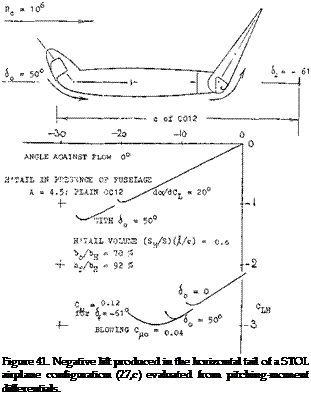
 A Horizontal Tail (suitable for a “high-lift” transport aircraft) is investigated in (27,c). During landing of a conventional airplane, the stabilizer is producing positive lift, while the elevator is trying to reduce the lift of the tail, possibly to zero. When this is no longer feasible, the stabilizer or the whole horizontal tail has to be trimmed down to a negative angle against the fuselage. There are then two reasons why elevator and horizontal tail of a really high-lift airplane (STOL) may be inadequate in size and/or effectiveness:
a) Deflection and/or extension of large and BL-controlled wing flaps necessarily produces large negative (nose-down) pitching moments.
b) Corresponding to the high lift coefficients obtained (say, CL = 4 or 5) the dynamic pressure at which the airplane is flying, is very low.
Of course, the wing flaps also produce increased down – wash, thus helping the tail to provide the negative (tail – down) lift required to counterbalance the wing’s pitching moment. Presence of, and interference by the fuselage is likely to reduce the average downwash, however. — In order to control a STOL-type airplane such as in (27,c) having a CL* above 6, and a Cm/4 in the order of 1.1, the tail surface as in figure 41, might be used. Including a nose flap with blowing around the “knee”, the maximum negative lift produced (in the presence of the fuselage) corresponds to CLH = — 3. Using a tail “volume” V = (.//c)(S^ /S) = 3.8 (0.28) = 1.06, the maximum Ditching moment produced by the tail is indicated by
Сш =VCLH = 1.06(3) = 3.2 (30)
Of course, to produce this value, the tail surface has to be trimmed to an angle of — 14°, against the flow. Only 1/3 of the value is needed, however, in the airplane considered; and that much can be obtained by means of the BL-controlled elevator, at a lesser angle of tail setting, and possibly without any nose flap at all. However, deflecting the nose flap, and blowing around its “knee”, would prevent stalling of the tail surface.
High-Lift Combinations. A leading-edge slat was investigated (32) in combination with various other high-lift devices. As partly shown in figure 43, the following values were obtained:
o
at oL = 17 for the plain airfoil
31° with leading-edge slat
16° with trailing-edge flap
24° with flap and slat
20° with upper-side blowing
34° with upper blowing and slat
21° with flap and upper blowing
31° with flap, upper blowing and slat
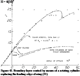
Rotating Cylinder. In figure 38 of Chapter V, it is shown how rotation of a cylinder placed within, or replacing the trailing edge of an airfoil, is an effective means of getting the flow around that edge. A similar method of boundary-layer control (preventing separation) at the leading edge, is illustrated in figure 42. Considering the very low Reynolds number (below 105) the maximum lift obtained for u/V = 3, is impressive. All traces of laminar separation (including a hysteresis loop, in the lower part of the graph) have disappeared. At higher speeds of rotation, the cylinder can be considered to be a pump. It then accelerates the surface flow; and its effect may be similar to that of gentle blowing.
Similar lift values were found when replacing upper-side blowing by area suction. As far as the slat is concerned, its effect is largest when the trailing edge is either not “strained”, or protected (by blowing or suction). The quality of stalling indicated in parentheses above shows the slat does not help when it is operating at high load. A basic principle to be learned from these experiments is that leading edge devices are not only useful to increase maximum lift and are needed to prevent sudden leading-edge stalling, but also that they should also be balanced in size and design, against any trailing-edge devices, so that stalling starts from that edge, slowly proceeding forward.
![]()
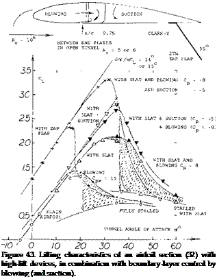 Blowing Around Leading Edge. Suction from the leading edge (and possibly suction from any place on the upper side of an airfoil) is characterized by a more or less abrupt stall. As shown in several examples in this chapter, blowing (from suitable places on the upper side) produces, on the other hand, comparatively gentle stalling. However, the ultimate in harmless stall, and in maintaining lift beyond its maximum, may be expected by imitating the cylinder in figure 42, using the so-called Coarrda effect (29); that is by blowing around the leading edge, from the lower to the upper side. In the experiments illustrated in figure 43, forward-facing slots were thus used located at 29 and 50%, respectively, of the chord. Dissipation of the jet sheet (primarily by mixing with the outside flow) was found to be so strong, however, that the maximum of its dynamic pressure is reduced to half, and its velocity to 1/4, at a distance equal to some 10% of the chord. For the slots investigated, therefore, a real increment of maximum lift v as not obtained. As demonstrated in the graph, the quality of stalling is definitely improved, however, from “abrupt” to “gentle”. In other words, lift is appreciably increased (say doubled, under certain conditions) at angles of attack beyond that where the lift is maximum. In one configuration (involving upper-surface suction, but not shown in the illustration) a hysteresis loop with a width of 6° of the angle of attack, is eliminated by lower-surface blowing (although C LX is reduced). In the case of the plain airfoil, strong blowing (corresponding to Cp = 15) is required to obtain the beneficial effect of lower-surface blowing. At higher lift coefficients (with Zap flap deflected) the effect is only found in combination with a leading-edge slat (evidently guiding the discharged flow around that edge). It is expected, however, that this type of blowing would be more effective and efficient when using a slot further forward (say at or even ahead of 10% of the chord).
(30) In figure 39, it should be noted that lift coefficients up to CLX =8, are only obtained with extremely high momentum coefficients (up to Cm. – 1.4). Such coefficients are typical of jet flaps as described in the “trailing edge” chapter. In effect, we have this type of flap in figures 38 and 39.
(31) Wolff, Rotating Cylinder in Leading Edge of Wing, Dutch Rpts RSL (Amsterdam); see translations NACA TM 307 & 354 (1926). [57]
CHAPTER VII –


