CLT2 Profile
The conclusions drawn in the previous section are valid for a conventional profile. Nowadays, the new profiles tend to have an increased lift coefficient and/or loading in order to reduce either number of blades per stage and/or a full stage of the LPT (Vazquez et al. 2003). These authors argued that lift coefficients higher than 1.2 and mean stage loading parameters higher than 3 were required to achieve a reduction of the number of components of the LPT. With the conventional technology, these new values would lead to an important efficiency penalty associated in part with increased profile losses.
The profile that will be presented next is a blade designed by ITP and it is representative of these new trends. This blade, CLT2, is a high turning profile designed to take account of unsteady inflow conditions. A large suction side separation bubble side occurs on the blade under steady inflow conditions. This bubble is suppressed in the presence of the wakes coming from an upstream blade row during a certain fraction of the wake passing period. Due
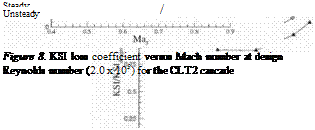
to compressibility effects, any suppression of a bubble is expected to be more beneficial in high speed fbws because of the reduction of blockage. Figure 8 presents the kinetic energy loss coefficient against Mach number under steady and unsteady inflow conditions. The results are shown for the design Reynolds numbers.
For the case under steady inflow, no dependency on Mach number is seen up to M3 = 0.76, from where the losses start to increase. According to Denton (1994), the losses associated with a passage shock wave are generally small unless the shock wave boundary layer interaction produces an earlier separation and therefore, an increase in the losses. For the current case, the first shock waves appear in the passage around Ma3 = 0.83. The increase of losses with Mach number is seen to appear at this Mach number because of the presence of the separation bubble and its increasing size.
 |
P
For the case of unsteady inflow, the losses seem to remain at a constant level at least up to Mach 0.76. The decrease in losses produced by the unsteadiness remains approximately constant for the range of Mach numbers under consideration. It is equivalent to approximately 14% of the steady loss. A benefit is therefore obtained up to Ma3 = 0.88, well within the transonic region.
It should be noticed that these experiments were carried out while keeping constant the rotational speed of the bars. So, the reduced frequency decreases when increasing the Mach number. Therefore, it might be expected that the curve of unsteady inflow conditions approaches that of steady inflow conditions when the Mach number increases. Instead, an approximately constant benefit is obtained for the entire range of Mach numbers under consideration. This is consistent with the suppression of a larger separation bubble at higher Mach numbers but lower reduced frequencies.
3. Conclusions
The techniques employed in the simulation of unsteadiness in high speed linear cascade testing have been presented and compared to the techniques involved in the low speed tests. Results from a high speed and a low speed cascade, both being models of an existing LPT blade have been compared for steady and unsteady fbw conditions. The results have shown that the same quantitative values of losses are obtained, showing the validity of the low speed approach for profiles with an exit Mach number of the order of 0.64.
The previous affirmation has been extended to a high turning profile designed following current design practices. Measurements of the losses have shown that there is no dependency on Mach number up to Ma3 = 0.76. A benefit coming from the wakes is achieved up to an exit Mach number of at least 0.9.
![]()


