Displacement Effect
3.2.1 Normal mass flux matching
 |
 |
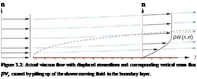
The major shortcoming of the simple inviscid model shown in Figure 3.1 is that it does not account for the displacement effect of the slower-moving fluid inside the boundary layer. This acts as a wedge, tilting and displacing the outer streamlines away from the wall, as shown in Figure 3.2.
This displacement changes the apparent flow tangency seen by the bulk flow, and thus modifies the overall flow-field. In the simple inviscid model this effect is ignored, which is the main reason for the discrepancies between the EIF’s and real flow’s edge velocity, wall pressure, and lift, shown in Figure 3.1. If the boundary layers are thin, then these discrepancies are small and are often ignored. But if the boundary layers are thick,
perhaps due to a low Reynolds number or the airfoil being close to or beyond stall, then the discrepancies between the real flow and the Simple Inviscid Model’s EIF may be unacceptably large.
To mostly eliminate these modeling errors, the EIF must be constructed so that its vertical mass flux equals that of the real flow outside the real boundary layer.
3.2.2 Normal mass flux in real flow
|
or pV(s, n) where m(s) S*(s) |
|
Пє (PeUe – pu) dn = peUe5* J0 >m і An |
Taking the d/ds derivative outside the integral is allowed provided the integrand is zero at the upper limit, which is the reason for the n>ne requirement for the final relation (3.6). The mass defect is the difference in the mass flow between the EIF and the real flow, integrated across the shear layer, and the displacement thickness is the resulting physical displacement of the potential flow away from the wall.
It must be stressed here that calculation of m(s) and S*(s) requires an analysis of the boundary layer itself, which will be treated in Chapter 4. Here they are assumed to be known properties of the boundary layer.


