
Our heavyweight helicopter equal in the world does not have
In Rostov started production of the most load-lifting rotary-wing car The Russian holding «Helicopt[...]

Everything about aircrafts and helicopters. News and events in aviation worldwide. Civil, transportation, military helicopters and airplanes.

Everything about aircrafts and helicopters. News and events in aviation worldwide. Civil, transportation, military helicopters and airplanes.

Everything about aircrafts and helicopters. News and events in aviation worldwide. Civil, transportation, military helicopters and airplanes.

Everything about aircrafts and helicopters. News and events in aviation worldwide. Civil, transportation, military helicopters and airplanes.


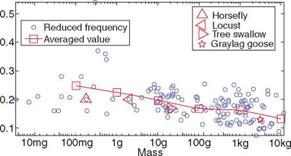
When analyzing a natural flyer’s aerodynamic performance, an important parameter is the ratio between the forward velocity and the flapping velocity, which is expressed in terms of the reduced frequency k,
where f, c, and Uref are, respectively, the flapping frequency, the mean chord length, and the reference velocity – in this case the flyer’s forward flight velocity. Unsteady effects increase as flapping frequency decreases, and therefore, depending on the forward velocity, different techniques have been devised to calculate the forces acting on a specific species.
In slow forward flight, both reduced frequency and wing-beat amplitude tend to be high, resulting in highly unsteady flow structures. In accordance with the Lifting Line Theory [64], the lift on a wing is related to the strength of the bound vortex. The trailing vortices (the tip vortices) are of the same circulation magnitude as the bound vortex. At the beginning or end of the downstroke, when the flapping velocity changes direction, a transverse vortex (starting or stopping vortex) is produced at the trailing edge, and according to Kelvin’s circulation theorem, these two transverse vortices connect the two tip vortices and result in the shedding of a vortex ring. Some flyers (for example, doves) make use of the clap-and-fling mechanism to generate the starting vortex and by this means reduce the delay in building up maximum lift during the first part of the downstroke. This mechanism is highlighted in Chapter 3.
In fast forward flight, the reduced frequency and the wing-beat amplitude tend to be low, and the wake consists of a pair of continuous undulating vortex tubes – or line vortices – approximately behind the wingtips. In such cases, it is not unusual for the outer part of the wing to be folded so that it aligns with the free-stream direction
Figure 1.24. Mass versus reduced frequency for birds and insects.
![]()
 (to reduce drag); when this occurs only the arm wing contributes to aerodynamic lift during the upstroke.
To evaluate flying animals’ lift and thrust, either unsteady or quasi-steady methods can be used depending on the magnitude of the reduced frequency. Early work by Ellington [65] showed that quasi-steady analysis substantially under-predicts the aerodynamic force needed to sustain the insect weight. As discussed in Chapters 3 and 4, much recent flapping wing research has focused on the understanding of unsteady aerodynamic mechanisms resulting from the wing movement. Figure 1.24 shows the correlation between a flyer’s mass and the reduced frequency. The data are based on those reported by Azuma [24] and Pennycuick [59], aided by the cruising – velocity estimate documented by Tennekes [29]. Overall, the reduced frequency decreases as the size and mass grow, indicating that small flyers are more unsteady in their flight than large flyers. Although this figure does not explain how they use this unsteadiness, it does indicate that unsteadiness plays a critical role in small flyers’ movement.
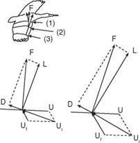
To quantify the lift and thrust generated by the flapping motion requires more sophisticated tools. However, we can understand the role of the unsteady effects by examining the relationship between the forward velocity and the flapping velocity in terms of the reduced frequency. It is also noted that different sections of the wing function differently in force generation. This concept can be better understood by introducing the relative flow velocity (Ur), defined as
Ur = U + Uf + w, (1-20)
where U is the forward velocity of the bird, Uf the flapping velocity, and wi the downwash (induced) velocity. The relative velocity determines the aerodynamic forces on the wing. For fast forward flight, the downwash velocity is small and can be largely neglected. As the wingspan increases, Uf increases and changes direction; consequently, the magnitude and direction on Ur change as well. Since Ur determines the resulting aerodynamic force F acting on each wing section along the span, F also changes in magnitude and direction. The changes can be seen in Figure 1.25.
It is commonly held that during the downstroke the inner part of the wing produces lift and drag, while the outer part produces lift and thrust. The net aerodynamic force produced by the wings during the downstroke is directed upward and forward, providing both lift and thrust. To obtain this favorable force distribution, the wings have to be twisted. By twisting the wings an optimal relative velocity can be
Figure 1.25. Velocity-vector diagram at different wingspan locations for fast forward flight. Here, the lift and drag are defined based on the effective velocity combining forward and local flapping velocities. For the entire vehicle, the lift is defined to be normal to the forward velocity (U) (i. e., in the vertical direction), and drag or thrust in the horizontal direction. According to the resulting force vector F illustrated here, drag of the vehicle is generated by the inner wing, and thrust of the vehicle is generated by the outer wing.
![]()
![]()
![]()

![]()
![]() obtained at each wing section throughout the wing stroke. Since the relative velocity determines the direction of the resultant aerodynamic force, this force is directed backward at the wing root and gradually turned forward when moving along the wingspan. At the wingtip region, the resultant aerodynamic force points toward the forward direction, giving both lift and thrust.
obtained at each wing section throughout the wing stroke. Since the relative velocity determines the direction of the resultant aerodynamic force, this force is directed backward at the wing root and gradually turned forward when moving along the wingspan. At the wingtip region, the resultant aerodynamic force points toward the forward direction, giving both lift and thrust.
Flying animals employ different mechanisms for various missions such as takeoff, landing, or gliding. Even during forward flight, they change their wing and body movements while flying through a range of speeds. Tobalske and Dial [8] analyzed high-speed (60 Hz) videotapes of black-billed magpies (Pica pica) flying at speeds of 4-14 m/s and of pigeons (Columbia livia) flying at 6-20 m/s in a wind tunnel. Pigeons have higher wing loading and higher aspect ratio wings compared with magpies. Both species alternate phases of steady-speed flight with phases of acceleration and deceleration, particularly at intermediate flight speeds. The birds modulate their wing-beat kinematics among these phases and frequently exhibit non-flapping phases while decelerating. During steady-speed flight, wing-beat frequency does not change appreciably with horizontal flight speed. Instead, with increasing flight speed the body angle relative to the horizontal decreases, thereby illustrating that the dominant function of wing flapping changes from weight support at slow speeds to positive thrust at fast speeds. Pigeons progressively flex their wings during glides as flight speed increases but never perform bounding. For magpies, the wingspan during glides does not vary with flight speed, but the percentage of bounding among non-flapping intervals increases with speed from 10-14 m/s. The use of non-flapping wing postures seems to be related to the gaits used during flapping and to the aspect ratio of the wings.
In general, the outer wing is mainly responsible for generating weight support and thrust, largely on the downstroke (see Fig. 1.26). For most birds, force generation is usually minimized on the upstroke to prevent excessive negative thrust. Furthermore, the shallow undulation of the inner wing areas cannot significantly contribute to thrust production (see Fig. 1.27a). However, the forces exerted on the inner wings can be used for weight support throughout the cycle without much penalty (see Fig. 1.27).
 |
Figure 1.26. Condor in fast flapping flight [66]. (a) Schematic of resultant forces acting on an outer or an inner wing during up – and downstrokes. (b) Asymmetric strokes of a pigeon in slow flight [67].
