HYDRODYNAMIC LIFT
Low-speed aerodynamics are often called hydrodynamics, simply meaning that compressibility of the fluid is negligibly small. As we will see, fluid-dynamic forces in water, are not necessarily similar to those in air, however, not even when disregarding cavitation.
A. FULLY SUBMERGED LIFTING
CHARACTERISTICS
All that has been said in previous chapters regarding boundary layer, Reynolds number, flow separation, lift or lateral forces of foils or control surfaces, also applies in liquids, such as water in particular. Although towing-tank tests are concentrating on “resistc. nce”(of ships, boats) information is also available on fins, rudders, control surfaces and their forces; and of course, hydrofoils.
REYNOLDS NUMBER. Since everything in a towing tank is usually geared to water-surface effects (waves) and the proper Froude number, Reynolds numbers are so low that appendages are not tested at all in typical investigations. Considering, for example, a hul model 10 ft long, representing a 500 ft long ship designed for a speed of 20 knots (34 ft/sec or some 10 m/s), th e maximum towing speed corresponds to
Ij = V/VgT = 34/V32 (500) = 0.27 (1)
This is the “first” hollow of the wave resistance function, for which most ships are designed. The resulting model speed is V = 1.5 ft/sec, and the Reynolds number is
R| = V7/V= 1.5(10) 10*71.25= 1.2{10)6
However, the R- number of any rudder, stabilizing fin, or for the appendages of a submarine would only be in die order of 50/o of that value, which is below 10/ Testing a rudder separately, and adding its forces to those of One ship, does not give realistic results either, because of the very considerable wake within which rudder (and propeller) are located. The problem of steering and oabilizing of ships is very often solved, relying heavily on statistics (past experience).
|
RUDDERS. To support the large forces originating in a rudder, its structural strength has to be adequate. Consider, for example, a destroyer (5,b) turning at full speed (say 35 knots = 60 ft/sec) and with full rudder (up to 35°). Conditions may then be as follows:
|
The data are based on / = 400 ft and l/h = 9. Considering, however, the boundary layer (along a planing bottom) the rudder force may be reduced to some 60o/°. The force is then in the order of 5°A of the ships displacement weight (assumed to be 4000 long tons). However, when
|
|
|
■г |
||
|
4\ч4ч\чуччччалуиии\у |
1 |
WIND TUNNEL WALL, , AW\WW V w V \ WXWxMWWV |
|
I Figure 1. Lift of a plain control surface or rudder tested in a wind tunnel (l, b) in combination with an end plate (wall). |
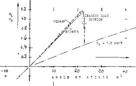
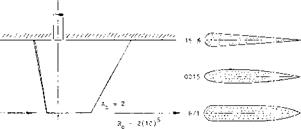
located within, or when flanking a propeller slipstream, the rudder force will be larger (5,b). The diameter of the rudder stock may be in the order of 1 or 2 it, in any larger ship. In hydrodynamic terms, a thickness ratio of t/c = 15% is considered to be “modern”. A number of such rudders (or control surfaces) have been tested (1) (6) (9) in wind tunnels. A convenient setup for doing such tests is to combine them with an endplate (or the wall of the test section), through which a rudderstock supports the model. Disregarding gap and boundary layer along the wall, the effective aspect ratio is then the “reflected” one, with a span b and an area twice the “exposed” dimensions. Figure 1 shows a typical example. The lift-curve slope corresponds to what is said in the “wing” chapters. At c* = 22°, the flow breaks down, evidently separating from the suction side. The maximum lift coefficient is almost CLk = 1.2. Considering the surface roughness usually found in ships, this value does not mean much, however. Lift due to leading edge suction is theoretically (7,a):
CU~CL M6+(0.2/A3A | (2)
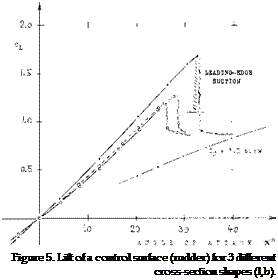
Cutting off the peaks in figures 1 and 5 accordingly, we may tentatively account for surface roughness. The result is a lift function similar to that in part (A) of figure 3. Beyond the angle of maximum lift, the normal force will take over. As suggested in the “stalling” chapter, this force may correspond to
C^ = 1.2 sine* (3)
where 1.2 = C^ = drag coefficient of a flat plate at c< = 90°. For example, at cx = 45°, the coefficient may be C^ = 0.85, and the lift component Cl = 0.60.
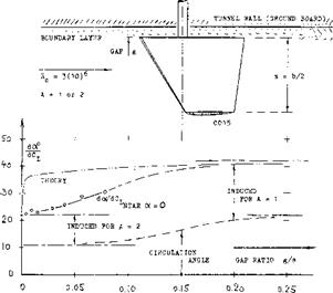
WALL GAP. Since the “wall” of a ship is usually curved, the structural gap may also open up as the fin is deflected. A “control surface” was tested (l, c) with gap ratios ‘g’/s up to some 10o/o. It is shown in figure 2, how the angle of attack (or deflection) required to produce a certain lift coefficient, increases as the gap is widened. As already stated in chapter VII of “Fluid-Dynamic Drag”, lifting-line theory is not confirmed at all. The flow through the gap is evidently restricted by separation. Eventually, the surface as in the illustration must be expected to assume a lift-curve slope corresponding to its exposed aspect ratio A = 1 (see the “wing” chapters).
ROLL-STABILIZING FINS have been introduced during the last decade to improve passenger comfort in a rolling sea (2). Such fins are half “wings” protruding from the hull in essentially lateral direction. Their angle of attack is automatically controlled by an electro – hydraulic system, sensing (and anticipating) angle and rate of the rolling motion. Some of the half “wings” tested (1) in wind tunnels, could be used as stabilizing fins. Lift-curve slopes and maximum lift correspond to what is said in the chapters dealing with “wings” and “stalling”. Of course, there is a boundary layer (the “friction belt”) around the hull of a ship. For example, at a position of 200 ft from the bow of a 500 ft long ship, the total thickness of the BL is in the order of at least 1.5°/o of the 200 ft, which is 3 ft. As described in chapter II of “Fluid-Dynamic Drag”, the corresponding displacement thickness is about 0.5 ft, and the momentum thickness is 0.3 ft (in comparison to a fin length of possibly 12 ft). Some fraction of these thicknesses, we might consider to be the equivalent of a gap. — When deflecting a pair of fins in the fashion of ailerons (one against the other) they interfere with each other, by producing a circulation, at least around the bottom of the hull. It is suggested that this interference be small.
SUBMARINES (8) have also horizontal fins called “planes”, for control and stabilization (9) of longitudinal up and down motions. Because of some secrecy about design and characteristics of such vessels (in all nations concerned) specific experimental data do not seem to be available. However, any pair of “stabilizing” planes located near the stern, can be treated in the same way as the horizontal tail of an airplane; see the chapter on “longitudinal stability”. In most submarines, a second pair of planes (8) was or still is installed near the bow. Its purpose is depth control (and faster diving). This is similar to that of a canard-type airplane (see in the “longitudinal” chapter). It must be assumed, however, that these forward planes made the boats unstable in pitch. Three men were required, accordingly, to maintain position and direction of motion, by means of manual control of planes and rudders. — For practical reasons, the forward planes had to be retractable. Beginning with the nuclear-powered “Skipjack”, and also in the “Washington” class of United States submarines, the conning tower was moved forward somewhat, and a pair of “fairwater planes” attached to its sides. The tip to tip span of these planes does not exceed the beam of the hull.
|
Figure 2. The influence of a “wall” gap upon the “lift angle” of a control surface (l, c). |
|
CONTROL FLAPS. Any control surface or fin as des – scribed above, is bound to start cavitating, at higher lift coefficients in a rolling sea. The use of a trailing edge flap is therefore desirable, providing the foil section with camber. We might even use a fixed fin with a servo – controlled flap. Half of the horizontal tail surface of an airplane shown in figure 3, is a good example for marine application. The thickness ratio at the root is t./c = 150/o (to withstand the large forces and bending moments in water) and the thickness is located at 47°^ of the chord (believed to be desirable to postpone cavitation). At the low Reynolds number Rc = 2(10) , the maximum coefficients are CL< = 0.73 for the plain surface at ex = 15°, and 0.67 when deflecting the flap to 25° at c* = zero. Considering, however, the motion of the water against the fin, possibly at an angle of cx = 12°, the maximum lift of the flapped surface corresponds to CL< =1.1. Torque or hinge moments of the flap can be found in the “control” chapter. |
a) Windsor, 4 Surfaces, Md Tunnel Rpt 320 (1961).
b) Whicker, Family of Fins, DTMB Rpt 933 (1938).
c) Windsor, With Gap, Univ Md Tunnel Rpt 453
d) Chaplin, Edge Ahead, TMB Rpt 944 (1954).
e) Windsor, Collection of Data, Univ Md Rpt 15*62-1.
(2) Chadwick, Mechanics of Roll Stabilization Fins with 53 References, Trans SNAME 1955 p 237; also “Wanderer” Trials, Sperry Gyroscope Rpt 1956.
(3) Saunders, Hydrodynamics in Ship Design (1957):
a) Volume I, Fluid Flow, Interactions, Hydrofoils.
b) Volume II, Fundamentals, Resistance, Design.
c) Volume III, Maneuvering and Wavegoing (1965).
d) Van Lammeren “Resistance-Propulsion-Steering” 1948.
RUDDER TORQUE. In wings, the pitching moment is primarily of interest for logitudinal stability and control. In rudders, this moment and/or the center of the normal forces represents the hinge moment or torque. As quoted, for example in (l, b), the center of pressure of the linear component of lift is at a distance from the leading edge (at the mean aerodynamic chord)
x/c = – (dCm./dCL) = 0.5 – (2 + V Az + 4 )/4(A + 2)
where the dot (•) indicates that the moment is defined about the leading edge. This function is plotted in figure
4. For example, when placing the stock at x/c = 0.15 of a rudder with A = 1, the torque is expected to be near minimum. Of course, at higher angles of deflection, and in smaller aspect ratios, the non-linear component contributes to lift. Its center may be at x/c – 0.7 of the lateral or lower edge of surface or rudder. As a consequence, a turning-back component of moment will develop. Such a moment is definitely present at really high angles of attack or deflection, where the flow is separated (stalled). Since forces in this condition are not steady (they fluctuate considerably) they are usually not tested in tunnel investigations as in (1). Reference (l, b) suggests, however, that at angles around 30° , the center of pressure is around 50^ of the chord, for a lift coefficient as estimated in figure 1. In conclusion, it is not possible to locate the stock of a rudder in such a manner that the torque would be near zero under all conditions of operation.
![]()
 FAIRING. Rounding the lateral edge of a control surface, or the lower edge of a rudder, reduces slope and maximum of the lift. It should be noted that in figure 1, the lift coefficients are referred to one and the same area (without the fairing). Considering area and aspect ratio, the loss – of lift due to round edge shape is as described in the “wing” chapter. When using half-round fairings, experiments and analysis as in (7,b) indicate that the effective span is approximately that of the trailing edge (Ц.). Also, the center of pressure moves forward. As shown in figure 4, the CP of rectangular wings using the 0015 (or any similar section) is then “at” the leading edge, for an aspect ratio Ц/с = 1. In terms of dCm./dC[^ = — x/c, such wings become unstable. In terms of rudder torque, rounding the lower edge reduces its magnitude, or even renders the moment “negative.” This is confirmed by experimental results in (l, b).
HULL WAKE. In conventional displacement ships, the whole rudder is functioning within the wide wake behind the hull. In propeller design, the reduced speed Vw is taken into account by means of the wake fraction
“W”=(V_VW)/V (4)
The fraction is quoted (3) to be between “w” = 0.2 and
0. 4 in single-screw ships. So, for “w” = 0.3, we obtain an average Vw /V = 0.7 at the rudder, and an average qw/q ^ 0.5. Considering, however, a ship in a steady turn (such as the airship in the “slender body” chapter) the rudder will, at least on the outside of the circle, be in or at the undisturbed flow.
|
ІТ– і і і T |
|
|
|
![]() " ‘ Cw = 1 .2 sin<y
" ‘ Cw = 1 .2 sin<y
![]()
![]()
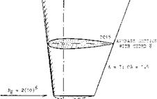
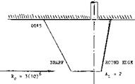
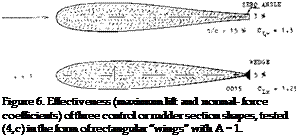
FOIL SECTION. Three cross-section shapes are shown in figure 5. As found in the “control” chapter, a straight and thin trailing “wedge” produces the highest lift. Other experimental rudder section shapes are presented in figure 6. It is seen again that a thin and straight (or hollow) trailing end improves the maximum lift. It is also expected that simply giving the 0015 section a blunt trailing edge, will increase effectiveness.
_)——– )———– 1—– >-
2o зо 4o
ANGLE OF ATTACK OC0
Figure 7. The “lift” of a rudder (or control surface) tested in astern direction (l, b).
ASTERN. Ships may also have to maneuver in the astern direction. The rudder is then exposed to full dynamic pressure (whatever there is at low speed). Figure 7 shows that the maximum force coefficient may be reduced to half of that in the forward direction.
SLIPSTREAM. Maneuverability of ships is evidently not sufficient, using rudders of the 2°i° size mentioned above, under “rudders". Usually, therefore, the rudder is placed in the middle of the propeller slipstream. Deflection of this stream provides steering even at ship speeds close to zero. As reported in (4,b) the following rudder-force ratios were observed:
0. 4 in the hull wake as against free flow
1. in wake, but with propeller, as against free flow 2.4 in slipstream as against without propeller 1.9 ditto, but in a steady turn
All these tests were made at a ship speed corresponding to Ej around 0.15. The 2.4 ratio is at the beginning of a turn, while in a steady turn (1.9) the angle of attack is naturally reduced (see the airship again). Statistical results are also listed in (5,c). The 180° turning “diameter” is in the order of “d”// = 3, for ships with the rudder in the propeller stream; and it is “d”// = 4 or larger, with a single rudder between twin screws. [66] [67] [68] [69] [70] [71]
COURSE STABILITY. Considering the hull of a ship to be the lower half of a streamline body, its destablizing moment can be estimated on the basis of what is said in the “streamline body” chapter. The moment corresponds theoretically to
Cm = ‘M’/qV = к sin(2cx) ^ 2k cX ^ 2 c< (5)
where к is in the order of 1.0, for more slender shapes. As such, the moment is proportional to the displacement volume V or the displacement weight Д. Consider, for example a freighter with
і = 400 ft overall length
V = 9000 tons displacement weight
V = 300,000 ft3 displaced volume
SR = 200 ft2 rudder area
The destabilizing moment may thus correspond to
‘M’/’q = 0.5 (2 V /3V/180) ^ 5,000 ((3°)
where (3 = angle of yaw, and 0.5 accounting for the heavy wake at the stern. The moment has to be balanced by that produced by devices such as fins, skegs, rudders at the stem of the hull. The stabilizing moment is proportional to rudder area (S^) times moment arm (x) to the CG. For the freighter considered above, with the CG or CB assumed to be at 0.4 of its length, the stabilizing moment is tentatively
‘M7q = – (1 – “w”)ftSR0.5/(dCL/d(3)(3 (6)
For “w” = 0.3. and (dCL/d(3°) = 1/20°, we obtain ‘M’/q = 1100 This is far below the destabilizing value.
We can assume, however, that the propeller provides stabilizing lateral forces. The hull itself (particularly whenTiaving a “V”, rather than “U” shaped stern) may also contribute to stability. Finally, the assumption of a moment arm equal to 0.55 (to the CG) may not be correct in dynamic analysis. Rather the ship can be assumed to yaw aboht a point ahead of the CG, which means that the ship is also drifting (in lateral direction) or sideslipping, when yawing. The extreme of this combination is found in steady turns (5,a). The point about which the ship is yawing, is thus ahead of the CG. Assuming that the point might be near the bow, we arrive at a stabilizing moment which might be sufficiently large. Nevertheless, ships are known to go all across the Atlantic with their rudders correcting the course continuously by means of plus and minus up to 5° deflections. Airships are reported to have been unstable; and it should be noted that their Frounde number was similar to that of ships, insofar as their density (in lb/ft3 of displacement) was equal to that of the surrounding fluid, just as in the case of ships.


