INFLUENCE OF COMPRESSIBILITY AT SUBSONIC SPEEDS
|
The Speed of Sound. The propagation of small disturbances of pressure, such as sound waves, occurs at the speed of sound which is given by a[58] = l/(dp/dp) = (dp/dp) = compressibility in (km /kg) 0) Since in a perfect gas, p ^ ^ , where к = 1.4 in air, the speed of sound is a = к р/р = к “R” T ~ 20 T(°K) (2) where “R” = “gas constant” = energy (kg m/sf ) per kg and (°K) = 29 in atmospheric air up to some 90 km of altitude. The speed thus increases with temperature. This means as well as others, that around a stagnation point, the speed (particularly in upstream direction) is increased, while in an area of reduced pressure (such as along the suction side of an airfoil) that speed is somewhat reduced. |

The compressibility of water is negligibly small for all speeds of vehicles (ships, boats, torpedos) even it they can go faster than 50 knots. Disregarding supersonic speeds, the compressibility of air (2) is so much greater that its influence upon aerodynamic characteristics must be taken into account at higher subsonic speeds.
1. PRINCIPLES OF COMPRESSIBLE FLUID FLOW
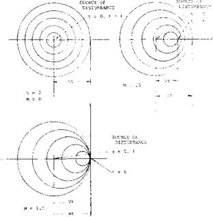
In a compressible fluid the propagation of pre ssure requires a finite amount of time to travel a given distance from the point of disturbance. This time is required as the disturbance travels at the local speed of sound relative to the body rather than instantaneously as assumed in incompressible flow. When the flight speed approaches the speed of sound the finite time element leads to changes in the flow pattern. This is illustrated in figure 1 showing the propagation of a disturbance moving at M = 0, .5 and 1.0. It is interesting to note how the disturbances pile up in front of the body as the Mach number approaches 1.0.
(1) Principles of compressible fluid flow:
a) Prandtl, “Essentials of Fluid-Dynamics”, London 1952.
b) Liepmann and Roshko, “Elements of Gasdynamics”, Wiley 1957.
c) Liepmann & Puckett, Aerodynamics of a Compressible Fluid, Wiley 1947.
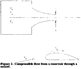
Impact Pressure. In considering the characteristics of compressible flow it is instructive to examine isentrcpic channel flow (l, c). If we consider a body at rest and the flow impinging on the body issuing from a reservoir, as illustrated in figure 2, it is possible to find relations in pressure, local speed of sound and density of use At the ultimate limit of subsonic flow where the local Mach number is 1.0 the following ratios are obtained:
 p0/p =1.9 absolute pressure
To/Т =1.20 absolute temperature
^/p =1.58 density ratio
a0/a = 1.10 speed of sound
q0/q =1.28 impact pressure
![]()
The subscript о in the above indicates the conditions in the reservoir, which is also the condition on impact of a Pitot tube.
The local dynamic or impact pressure q is related to the local static pressure and Mach number by the equation
q=l/2?V2 = a^pM/2 (3)
The impact pressure can also be related to the difference between the reservoir pressure and the static pressure as a function of the Mach number
pc – p/q = 1 + (M2/4) + (M4/40)
– 1.09 (CM = .6 = 1.219 @M = .9
It should be noted that the dynamic pressure used in the coefficients such as CL are still based upon the “dynamic” pressure q. This pressure
q = 0.5 p (M2) a2 = 0.5 p Vе’ (5)
(where all quantities are those in the ambient flow) is then a “potential” of the undisturbed flow, rather than a pressure differential which can directly be measured with the aid of a Pitot-static or Prandtl tube. In fact, there is some difficulty in wind-tunnel testing, in determining M’number, temperature and density.
As far as lift is concerned, the impact pressure as such is usually not considered, although it has consequences upon the pressure distribution of airfoil sections and wings (lifting or not lifting).
Prandtl-Glauert Rule (3). When approaching a wing, the air particles within a certain sheet of the stream slow’ down. They continue to be slowed down at the lower side of that wing, when it is lifting. As explained above, the pressure corresponding to reduced velocity is increased above that as expected according to Bernoulli’s law of aerodynamic (or hydrodynamic) motion. What was said about the time required for pressure to propagate, also holds for negative pressure differentials as at the upper side of an airfoil (due to thickness as well as due to lift). To explain this phenomenon, it can also be said that the air particles do not have the proper time to be deflected around the convex upper surface of a lifting wing. As a consequence, the values of all pressure differentials and of the resulting normal or lift forces, increase as a function of the Mach number. As found by Prandtl (l, a), by Glauert (3,a) and probably by others, all differentials of the pressure and lift coefficients are approximately proportional to the Prandtl-Glauert factor.
і ip – і / Ci — m2 (6)
In reality, 1 – 00 is never reached at M = 1, neither at the
stagnation point (where C p max = 1.28) nor at the suction side of airfoils (where vacuum is the extreme limit, with C pmin = — 1-43,’at M = 1).
Critical Velocity. We have considered static pressure above. For small variations along slender bodies or on airfoil sections at small lift coefficients the velocity differentials are approximately:
ZW/V = – 0.5 Cp
However, at higher Mach numbers conditions are more complicated. In this text, maximum velocity around a body or wing is of particular interest as it may locally reach the speed of sound. This speed, in turn, is a function of the temperature at the point of maximum speed (or minimum pressure). The flow around the nose and past the suction side of a lifting airfoil is the same as that through a Laval nozzle (l, a,b). At the stagnation point we have the absolute “total” or reservoir pressure p. From there, an expansion takes place. As in the smallest cross section of the nozzle, the speed of sound is reached at some point at the suction side, where p or Cp obtain their critical values, so that the local number = 1. In air, conditions at that point (subscript x) are indicated by the following constant ratios:
|
Px/P. |
= 0.528 |
absolute pressure |
|
Tx/T. |
= 0.833 |
absolute temperature |
|
ал/а# |
= 0.913 |
local speed of sound |
|
PxC. |
= 0.634 |
density ratio |
where the subscript (• ) refers to the reservoir c ondition (with V = 0) from where the flow originated (such as in the pressure tank of a wind tunnel, or in a stagnation point).
Critical Mach Number. The relations of the listed, to the “ambient” quantities in the undisturbed flow to which airfoil or body are exposed, may be found in texts such as (T, a,b). The critical Mach number is defined as that where C first reaches the critical negative value, that is where at a particular point of the surface the local speed of sound (corresponding to M^ = Vx /ax = 1) is first attained. These values of critical pressure and ambient Mach number for M local equal to 1 may be found from the equations
Px /q = (0.75/Мг) (1 + 0,2 M2fb
(7)
C Pmin =(p /q)-(1.43/M2)


