Inlet conditions to the cascade
The time mean conditions at inlet to the cascade are affected by the bars. These effects are due to the creation of entropy by the bars and work done by the component of the drag force of the bars in the direction of movement of the bars. In the ideal case, the time mean conditions at the inlet of the cascade can be measured by placing probes downstream of the bars. However, the distance between the bars and the leading edges of the cascade is usually small (25-50% of the chord). Therefore, access is difficult, especially in small scale, high speed cascades. Furthermore, the fbw is unsteady. This can result in false readings from conventional instrumentation. Also, due to the presence of the blades, the time-mean inlet stagnation conditions may not be pitchwise uniform in the unsteady ft>ws (Hodson and Dawes, 1996). To avoid these problems, a calculation procedure is used to determine the (mixed out) conditions downstream of the bars.
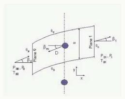
A control volume representing the ft>w through the row of bars, in the relative frame of reference, is shown in figure 2. The drag force, D, represents the force produced by the bars on the fhid. It is taken to act against a direction averaged with both inlet an exit directions. This model is a modified version of the model proposed by Schulte and Hodson (1996). In their model an incompressible analysis of the same control volume is made, assuming that D acts in the same direction as the flow entering in the control volume. The validation
of this method for incompressible fbw can be found in Schulte (1995). The validation for compressible ft>w is presented below.
The drag coefficient of the bars, Cd, is defined by
Cd = D/(d • (Poo, rei – Pso)) (4)
and
tan^m = (tanfo + tanfi i)/2 (5)
defines the direction against which the drag force acts.
On surfaces Sb and Sd, periodic boundary conditions apply and no net ft>w crosses these surfaces. Flow enters the control volume with a uniform velocity through surface Sa and leaves the control volume through surface Sc. It is assumed that mixed out conditions are already reached at surface Sc. The continuity, momentum and energy equations form an implicit system of equations that have to be solved for each inlet condition.
The solution to the system of equations depends, amongst others, on the drag coefficient of the bars, Cd. The value of Cd depends on the conditions at plane 0. Therefore, in order to solve the system of equations, the value of Cd has to be known for the range of Reynolds numbers and Mach numbers found in the measurements.
For the determination of Cd, the drag force produced by the bars, D, must be known. To measure D, the wake of one single stationary bar was traversed. Knowing the drag force, the drag coefficient of the bar can be calculated using (4). The value of Cd was measured for the entire range of Reynolds and Mach numbers covered by the measurements. By knowing the value of Cd, the implicit system of equations can be solved for a given value of the conditions upstream the bars and flow angle. Thus, the mixed out conditions downstream the bars can be determined.
|
Figure 2. Control volume. Frame of reference fixed to the bars |
The calculation of the conditions downstream of the moving bars will be now validated with experimental results. The measurements were performed in the high speed rotating bar rig. The cascade was removed and a pneumatic probe was placed downstream of the bars. The probe was placed in the plane where the leading edges of the cascade would have been. The conditions upstream the bars corresponded to the design inlet conditions of the cascade.
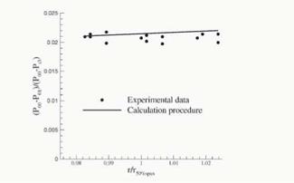
Downstream of the bars, the probe was traversed in the pitchwise direction at three different spanwise positions. The measured upstream conditions are used to calculate the conditions downstream of the bars by means of the calculation procedure described above. A comparison between the downstream measurements and the calculated values is shown in figure 3. The abscissa represents the radius of the bars at each measurement point. This value is non-dimensionalised by the radius of the bars at 50% of the span and at a pitchwise position that would correspond to the centre of the cascade. The ordinate represents the reduction in stagnation pressure through the row of bars expressed as a fraction of the equivalent exit dynamic pressure of the datum high speed cascade at design conditions. At r/r50%span equal to 1, the differences between prediction and experiments are less than 0.1% of the cascade exit dynamic pressure. A good agreement between the calculation procedure and the measurements is found, thus validating the method.
|
Figure 3. Comparison of experimental data and calculations for the loss of stagnation pressure across the bars at design conditions of the cascade, Re3 = 1.9 x 10⁵, Ma3 = 0.64 |


