. STRAIGHT WINGS AS USED IN HIGH-SPEED AIRPLANES
The influence of compressibility on the characte ristics of wings, and considerations when using them in airplanes, are different to a degree from what is presented on airfoil sections.
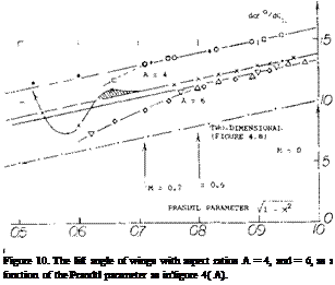
Lift Angle. Applying the Prandtl-Glauert rule to the sectional component of the angle of attack (as in flgure 4) the “lift angle” of wings with higher aspect ratios (say above 4) as presented in the “wing” chapter can be formulated as follows:
doC/dCu =1о7ГПмГг + (К/A) (16)
where К = 20 or somewhat larger, and VI—M :: 1/“P”. Experimental results of wings with higher aspect ratios are plotted in figure 10, as a function of this parameter. A straight-line function is thus obtained for equation (16). For A = 6, agreement is found above 71 — Мг = 0.8, that is at M’numbers below 0.6. The experimental points for the wing with A = 4, can be matched by the equation when using the constant К = 24.
|
|
Smaller Aspect Ratios. In order to include aspect ratios, say below A – 4, the formulation as in (10,a) is preferable. To take compressibility into account, the parameters to be plotted are
(10° (dCL /doc)//1 – M*>
and
(“F” = A /1 – M2 /0.9) (17)
where 10 = (2тс/а)(rr/180). The function of the Prandtl factor “P” – 1 / 71 -M2 can be understood to be that of increasing the effectiveness a = CL<*/2 7Ґ. This ratio is increased from about 0.9 to (a “P”). In a formulation similar to that in (10,a):
(dCL /doc )/(0.1 f� Мг) =
“F’7(2 + Of,7+ 4~) (18)
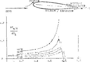
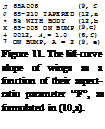
where “F” as in equation (17) contains the Mach number. Available experimental results are plotted in figure 11 with the results at M’numbers above the critical excluded. Since the value of the modified aspect ratio “F” is a function both of the geometric ratio and the Mach number, confirmation of the influence of compressibility is not directly evident. Examination of individual points seems to show that lift-curve slopes at higher Mach numbers tend to be slightly higher than expected. On the other hand, airfoil sections (5,h) such as 0015 and 0018, also lose lift as a consequence of an area of high-speed flow (suction as indicted in figure 8) developing not only on the upper, but also on the well-rounded lower side. Negative pressures of this kind are shown in (5,f & g), while at the same time boundary-layer losses are growing along the upper side (incipient separation from the trailing edge). Wings with such sections are not included in figure 11.
 |
AT cx = 4 AND M

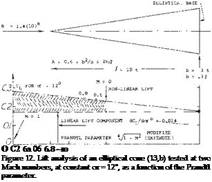
 The lift coefficient of a slender cone, at constant of – 12 , is plotted in figure 12 as a function of Уі — M. Here, as in the evaluation of other bodies (13) with aspect ratios between 0.3 and 0.6, it is found that the modified factor gives good results matching the experimental differentials of the lift coefficient. Of course, somewhere around M = 0.9, the factor (approaching infinity at M = 1) should no longer be expected to be applicable.
Tail Surfaces. Tail surfaces, horizontal or vertical, are basically “wings”. Elevators and rudders are trialing-edge flaps. The lift-curve slope of tail surfaces is influened by the fuselage (to which these surfaces are attached) and is accounted for as explained in the “control surface” chapter. It can be expected (dot /d6) their effectiveness may remain unaffected by compressibility. This means that the lift due to flap deflection increases with the Mach number at the same rate as (dCL/dctf). The lift angles of a particular surface are plotted in figure 13. The line through the (d6/dCL ) data happens to have ordinates 1.5 times those through the (doc /dCL ) points. Therefore, dot /d6 = 2/3, a ratio which for a 30% flap is at the upper limit of what is shown on figure 2 of the “control” chapter.
![]()
|
10 (dCL/dc* |
|
|
|
|
|
|

![]()
as in figure 11, without any influence of compressibility. However, it is not known yet how the second, non-linear component as presented in the “body” chapter may vary as a function of the Mach number. Since a slender wing is closer to a three-dimensional body than to a lifting line, it is suggested to use the modified Prandtl factor as derived from (3,f) in chapter XV of “Fluid-Dynamic Drag” in the simplified form of
“P” = i /УГЛА (20)
![]()
Control Flap. The pitching moment produced by a flap (keeping Cl. = zero) is shown in figure 14. It varies in proportion to the Prandtl-Glauert factor (equation 6). The value extrapolated to “P” = 1, which means M = 0, agrees with those plotted in figure 4 of the “control” chapter. The hinge moment of the flap is also tested in (14,b). At deflections below 6=7, this moment is found to be independent of the Mach number. At 6 above 8 , it seems to increase in proportion to “P”. All moments considered continue to grow (or they remain constant, as the case may be) for some interval beyond the critical Mach number. Pressure distributions as in (14,b) show the peaks as suggested in figure 14. Depending upon lift coefficient and flap deflection, the critical Mach number can thus be encountered either at the leading edge, or in the vicinity of the maximum thickness, or around the hinge line of the flap.
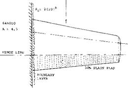
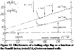 Wing Flaps “always” cover only part of the span. Their characteristics can be considered in terms of two – dimensional flow, that is in reference to the airfoil section from which they are deflected. It is suggested to use the principle as demonstrated in figure 13, together with the part-span function as in figure 21 of Chapter V, to determine the lift-increasing effect of wing flaps. This procedure amounts to increasing lift and lift-curve slope in proportion to the Prandtl-Glauert factor. The span wise lift or load distribution is particularly treated in (10,b).
 Critical Lift. Airplanes flying at high speeds normally operate with reduced lift. Consider an airplane cruising at M = 0.8, at 9 km or 30,000 ft. At this altitude, the speed of sound is reduced to 0.9 of that at sea level. At the same time the atmospheric density is reduced to less than 40%, so that the lift coefficient required to support the craft may be between 0.3 and 0.4. Under these conditions, with a Prandtl factor “P” = 1/0.6 = 1.7 or higher, the minimum pressure at the suction side may be between that as indicated by equations (10) and (11), say C pmm = -0.25 —0.25 = —0.5; and that as in figure 6, say Cpmjn = —1.0. The critical Mach number is 0.7, accordingly, for a properly cambered section; or Mcnt = 0.6 for a symmetrical section. In conclusion, the permissible M’number can be below the 0.8 as assumed above. Of course, with 30 of sweep, the 0.8 is reduced to an effective value of 0.8 cos30P = 0.7; see the Chapter XV on swept wings. [60]


