SURFACE DISTRIBUTION OF THE BASIC SOLUTIONS
The results of Sections 3.2 and 3.3 indicate that a solution to the flow over arbitrary bodies can be obtained by distributing elementary singularity solutions over the modeled surfaces. Prior to applying this method to practical problems, the nature of each of the elementary solutions needs to be investigated. For simplicity, the two-dimensional point elements will be distributed continuously along the x axis in the region x1—*x2-
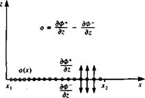
SOURCE DISTRIBUTION. Consider the source distribution of strength per length o(x) along the x axis as shown in Fig. 3.19. The influence of this distribution at a point P(x, z) is an integral of the influences of all the point elements: . fX2
Ф(х, 2) = 2л J 0(<X^ ІП “ *o)2 + z2 dxо (3.130)
(ЗШ)
z^“ <3132)
In order to investigate the properties of such a distribution for future modeling purposes, the type of discontinuity across the surface needs to be
 FIGURE 3.19
Source distribution along the x axis.
![]()
![]() Гк, зф +
Гк, зф +
[Note—-
|
w(x, 0+) = lim z—*-0+ |
|
, (x – *o)2 + Z |
examined. Since each source emits fluid in all directions, intuitively we can see that the resulting velocity will be away from the surface, as shown in Fig. 3.19. From the figure it is clear that there is a discontinuity in the w component at 2 = 0. Note that as z-»0 the integrand in Eq. (3.132) is zero except when x0 = x. Therefore, the value of the integral depends only on the contribution from this point. Consequently, o(x0) can be moved out of the integral and replaced by a(x). This suggests that the limits of integration do not affect the value of the integral and for convenience can be replaced by T®. Also, from the z dependence of the integrand in Eq. (3.132), the velocity component when approaching z = 0 from above the x axis, w+, is in the opposite direction to w~, which is the component when approaching the axis from below. For the velocity component w+, Eq. (3.132) becomes
To evaluate this integral it is convenient to introduce a new integration variable A,
л._*!
z z
 |
and the integration limits for z—*0+ become ±®. The transformed integral becomes
FIGURE 3.20
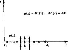
 Doublet distribution along the x axis.
|
distribution, pointing in the z direction [p = (0, ft)], at a point P(x, z) is an
|
|
Ф(*, 0±) = T |
Note that the velocity potential in Eq. (3.137) is identical in form to the w component of the source (Eq. (3.132)). Approaching the surface, at z = 0±, this element creates a jump in the velocity potential. This analogy yields
 |
This leads to a discontinuous tangential velocity component given by
Since the doublet distribution begins at the circulation Г(дс) around a path surrounding the segment is
![]()
![]() Г(дс) = f и(дс„, 0+) dx0 + f ы(х0, 0-) dx0 = – fi(x)
Г(дс) = f и(дс„, 0+) dx0 + f ы(х0, 0-) dx0 = – fi(x)
Лі Jx
which is equivalent to the jump in the potential
Г(дг) = Ф(дс, 0+) – Ф(*, 0—) = – fi(х) = ДФ(дс)
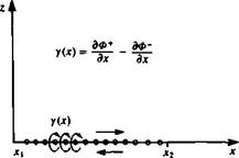
VORTEX DISTRIBUTION. In a similar manner the influence of a vortex
FIGURE 3.21
 Vortex distribution along the x axis.
distribution at a point P(x, z) is an integral of the influences of the point elements between xx—*x2 (Fig. 3.21).
Ф(дс, z) = -— f y(x0) tan-1 – — dx0 (3.144)
•’xj Др — X0
(3145)
"<*• гЫ Tx s <3146>
Here the и component of the velocity is similar in form to Eqs. (3.132) and (3.137) and there is a jump in this component as z = 0±. The tangential velocity component is then
u(x, 0±) = — (x,0±) = ±?y (3.147)
The contribution of this velocity jump to the potential jump, assuming that Ф = 0 ahead of the vortex distribution is
ДФ(дг) = Ф(дс, 0+)-Ф(дг, 0-) = J ^~dx0-j – y-~dx0
The circulation Г is the closed integral of u(x, 0) dx which is equivalent to that of Eq. (3.142). Therefore,
Г(х) = Ф(х, 0+) – Ф(х, 0-) = ДФ(х) (3.148)
Note that similar flow conditions can be modeled by either a vortex or a doublet distribution and the relation between these two distributions is
![]() (3.149)
(3.149)
Comparing Eq. (3.141) with Eq. (3.147) indicates that a vortex distribution can be replaced by an equivalent doublet distribution such that


