Swept and Oblique Wings
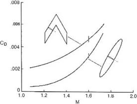
For high speeds, swept wings are used since the velocity component normal to the leading edge determines the aerodynamic performance of the wing. R. T. Jones [11, 12] claims, based on theoretical and experimental results, that oblique wings are better, see Fig. 7.11.
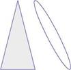
Comparison with a delta wing is also shown in Fig. 7.12.
Jones used Kogan’s theory [13] to determine minimum drag of elliptic wings. For details, see Ref. [11].
7.3 Wing-Body Combinations
A body of revolution, carrying plane wings of small aspect ratio can be analyzed using the results of the previous sections, via the Joukowski transformation. Consider a mid-winged body of revolution as in Fig.7.13.
 |
For the calculation of the lift, we will follow Spreiter [14], who solved the cross flow problem by mapping the cylinder onto the Y-axis using
![]()
![]()
![]()
![]()
 Fig. 7.12 Drag due to lift: oblique elliptic wing and delta wing, M = 2
|
|||
|
|||
|
|||
|
|
||
|
|||
![]()
Usina
Fig. 7.14 Mapping of wing-body cross section onto the Y coordinate axis
|
|
The wings map also onto the Y-axis and the wing edges are located at Y = ±2(1 + b2) = Fig. 7.14.
The problem of the flow normal to a flat plate has been discussed before (the flow over a flat plate is related to a flow over a cylinder).
It should be mentioned that the two-dimensional cross flow solution is unrealistic, since the flow will separate at the plate edges. With a three-dimensional slender wing-body configuration, the axial flow keeps the cross flow from separating so the potential solution is a good approximation, for small angles of attack.
Spreiter [14] obtained the following result for the lift (see also Ashley and Landhal [1]):
2/b2 2 4R4
L = npU2 4 – R2 + 42 a (7.99)
Special cases of the body alone or the wing alone are included in this formula. To estimate the effect of the fuselage on total lift, i. e. body interference, consider the ratio
 Lw+b Lw
|
|
|
|
 |
|
|
|

![]()
![]()
where D0 is the wave drag at zero incidence.
 The drag for subsonic flow reduces to induced drag R = 0, it becomes
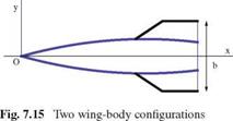
The above formulas are valid for two types of configurations: a body of revolution having general cross section with wings whose edges are everywhere leading edges, and for a body of revolution with a uniform cross section downstream from the section of maximum wing span, as shown in the following sketches, Fig. 7.15.
For the case of an uncambered wing with swept-forward trailing edges, the lift on sections behind that of maximum span is zero in the present approximation and b is replaced by bmax in the above formulas.
In the case of swept-back trailing edges, as for an arrowhead wing, the analysis requires the solution of hyper integral equations (seeMangler [15]). See also Brandao [16].
For supersonic flows past bodies of revolution, when S’ (x) is discontinuous, the reader is referred to the work of Lighthill [17].
For ducted bodies of revolution with annular intakes, see Ward [18-20].


