The aerodynamics of propellers
The advent of V/STOL aircraft has resurrected in part the subject of propeller aerodynamics which was buried by the development of the turbojet engine. This chapter deals only with the propeller at zero angle of attack, that is, where its axis of rotation is aligned with the free-stream velocity. Corrections for angle of attack are developed in Chapter 8.
Classical Momentum Theory
Considerable insight into the action of propellers can be gained by the application of the momentum and energy principles developed in Chapter 2.
|
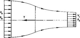
Fig. 4-1. Streamtube passing through a propeller. |
Consider the thrusting propeller shown in Fig. 4-1. In this simplified model the following is assumed:
1. The thrust loading is uniform over the propeller disk. This implies the limiting case of an infinite number of blades.
2. There is no rotation imparted to the flow. This would be approximated by a pair of counterrotating propellers.
73
3. A well-defined slipstream separates the flow passing through the propeller disk from that outside the disk.
4. Far ahead of and behind the propeller the static pressure in and out of the slipstream is equal to the undisturbed free-stream static pressure.
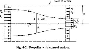
Consider a cylindrical control surface of radius R around the propeller, as shown in Fig. 4-2. R is assumed to be large in comparison to the propeller radius. The upstream and downstream planes are infinitely far removed from the propeller so that the propeller streamtube walls are parallel to the axis. The static pressure is constant in these planes and equal to the free – stream static pressure p0.
|
|
From continuity there must be a flow in through the side walls. This flux, Q, is given by
Q = V2nr2 + V0n(R2 – r2) – V0nR2 (4-1)
or
Q = nrV2 – V0). (4-2)
For large R the streamlines are nearly parallel to the axis. The transport of momentum in through the walls in the direction of the axis is thus pV0Q. Applying the momentum theorem, we therefore obtain
T — momentum flux out — momentum flux in,
or
T = nr2pV + n(R2 – r2)pV2 – ;tR2pV2 – nr2p(V2 – V0)V0, (4-3) or
T = pnr2V2(V2 – V0). (4-4)
In words these equations state that the propeller thrust is equal to the product of the mass rate of flow through the propeller and the increase in
velocity in the slipstream infinitely far in front of and behind the propeller.
Although the result may seem obvious, we cannot arrive at it simply by considering the propeller slipstream as a control surface. If such a procedure were done, the resultant of the static pressure acting on this surface in the thrust direction would have to be considered.
Now the thrust can also be expressed as
T = A Ap, (4-5)
where A is the propeller disk area and Ap is the discontinuous increase in the static (and total) pressure across the disk. Ap can be obtained by writing Bernoulli’s equation in front of and behind the propeller disk. The equation does not hold, of course, across the disk.
Po + ЇРУ о = P + ?pV
Po + kpv = P + ЇРУ і + Да
or
= W – Vl)
![]() = kiP(V2 – V0)(V2 + V0).
= kiP(V2 – V0)(V2 + V0).
Also from continuity
nr2V2 = AV1.
Hence by combining (4-4) through (4-7)
V.-4*-
This important result of the momentum theory of propellers states that the velocity through a propeller is equal to the average of the velocities in its slipstream infinitely far in front of and behind the propeller. The increment added by the propeller to V0 at the disk, that is, V1 — V0, is referred to as the induced velocity w. In terms of w Eq. (4-4) with the aid of (4-8) becomes
T = pA(V0 + w)2w. (4-9)
This expression is easily remembered, for pA(V0 + w) is the mass rate of flow through the disk and 2w is the ultimate change in velocity of the flow.
In order to define an efficiency, expressions are needed for the power required by the propeller and the useful work it performs. By neglecting profile drag losses and losses associated with the trailing vortex system and applying the energy theorem to control surfaces far ahead of and behind the propeller, we evaluate the power that the propeller supplies to the fluid
as the difference in the flux of kinetic energy passing through the control surfaces.
P. = ±pA(V0 + w)l(V0 + 2w)2 – Ко]
= _pA(V0 + w)2w](V0 + w)
= T(V0 + xv). (4-10)
Hence the power supplied to the flow is simply the product of the propeller thrust and the local velocity at the point at which the thrust is being produced.
The useful power is defined as the product of the thrust and the free stream, or advance, velocity V0.
Puse = TV0.
Hence an ideal efficiency, щ, can be defined as
![]() 1
1
1 + w/K0
The dimensionless velocity ratio, hence tfr, is purely a function of the propeller disk loading T/A divided by the dynamic pressure pV 1/2. If we define a dimensionless thrust coefficient CT by
then from (4-9) the induced velocity becomes
![]() XV, /———
XV, /———
– = і(УГТСг – і).
An induced or ideal power coefficient, CPi, can also be defined by
C =_5_.
P’ У AVI
With the help of (4-10), this can be written as
![]() — – у-(Л + Cr + 1);
— – у-(Л + Cr + 1);
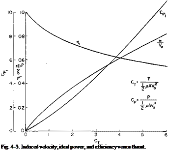
w/K0, CP(, and ri are presented in Fig. 4-3 as a function of CT. For a given
|
In a statically thrusting propeller CT, CPi, and >/, V0 = 0. For this case Eqs. (4-9) and (4-10) become |
are meaningless, for |
|
( T y/2 |
|
|
W-{2Pa) ’ |
(4-15) |
|
J3/2 |
|
|
s/2pA |
(4-16) |
|
CT, these are the minimum values of CP or maximum values of which we can hope to obtain from a propeller. |
 |
Prediction of Thrust Available as a Function of Forward Speed
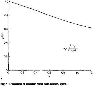
In the calculation of takeoff distance the variation of thrust with forward speed is required, and the momentum theory can provide a quick estimate of the available thrust. If it is assumed that the power required to overcome the profile drag of the blades and the power available from the engine do not vary with forward speed, the induced power absorbed by the propeller will be a constant. If a sub 0 refers to static conditions, then by equating (4-14) and (4-16) we have
This can be expressed as
 |
The variation of thrust with forward speed, obtained from (4-17), is shown in Fig. 4-4. It will be observed that the available thrust decreases as the forward velocity increases.
Dynamic Pressure in Slipstream
One final item of interest, readily obtainable from momentum theory, is the dynamic pressure infinitely far downstream of the propeller in the slipstream:
Чаэ = iP(V0 + 2 w)2.
From (4-9)
so that
![]()
![]() (4-18)
(4-18)
Thus it is noted, and easily remembered, that the dynamic pressure in the ultimate wake of a propeller is equal to the free-stream dynamic pressure plus the disk loading T/А.


