THE EFFECT OF ELASTIC DEFORMATION ON THE LIFT DISTRIBUTION
For a wing of small aspect ratio, or arbitrary planform, or with large cutouts, or subject to serious effect of warping restraint at the wing root, it is necessary to consider the entire deflection surface of the wing (instead of assuming rigid chordwise sections), and to compute the lift distribution by a lifting-surface theory. In this case the problem of determining the effect of the elastic deformation on the lift distribution can be formulated
и
|
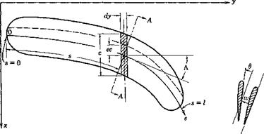
A-A Fig. 4.7. A slender wing. |
by means of influence functions into integral equations of two independent variables (involving double integrals). In most practical cases, however, the warping of the chordwise sections is not of great importance, and reasonable accuracy can be obtained by considering the deformation pattern at each chordwise section as characterized by a deflection at a reference point and a rotation in the chordwise section about that point.
For a wing other than a normal simple beam, the concept of elastic axis loses its simplicity, and it becomes more straightforward to define the wing deformation with respect to an arbitrary reference line. As remarked in § 3.2, when an arbitrary reference line is used, two influence functions are required to specify the wing rotation and two others to specify the wing deflection. As an example, consider a wing of large aspect ratio whose cross sections normal to a reference line may be
assumed rigid. Let s be the distance measured from an origin along the reference line (see Fig. 4.7). Let w(j) be the deflection at a point s on the reference line, normal to the plane of the wing (the wing is assumed to be planar, and the displacement in the plane of the wing is assumed to be negligible), and let 6(s) be the angle of twist of a normal cross section at s about the reference line. In the lift-distribution problem, the slope dw/ds, rather than w itself, is of importance. The elastic property of the wing can be characterized by the following influence functions:
|
Fi(s, о), |
. . dw giving — ds |
at s |
due to a unit force at о |
|
F2(s, o), |
giving в |
at 5 |
due to a unit force at a |
|
Hi(s, <r), |
. . dw giving- |
at 5 |
due to a unit external twisting moment at о |
|
H2(s, o), |
giving в |
at s |
due to a unit external twisting moment at о |
By an external twisting moment at the point a is meant a couple whose vector is tangent to the reference line at the point o. If there acts a unit couple at a whose vector is perpendicular to the reference line at a, which will be referred to as a unit external bending moment, the deflection surface can be obtained from the following influence functions:*
SFjCs, o) giving dw/ds at s due to a unit external bending moment do ’ at о
giving в at 5 due to a unit external bending moment at о do
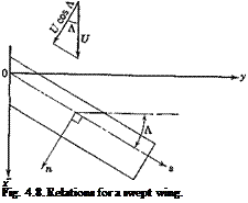
In defining these influence functions, the structure is assumed to be rigidly supported in a manner appropriate to the particular problem under consideration (cf. footnote, p. 19). In order to define the positive senses of-w, 6 etc., we define a set of local orthogonal coordinates (n, s), with s tangent to the reference axis and n normal to it; n is to s as x is to у axis (see Figs. 4.7 and 4.8). The senses of the force and deflection agree, and
* This can be easily verified by considering a bending couple as the limit of a pair of equal and opposite forces, the magnitude of which increases as the distance between them decreases, in such a way that a unit moment is maintained. Thus the slope 3w/3s at a point s due to a force M/Aa acting at a – f Дег/2 and another force — M/Ao at о — Ao/2 is
![]()
![]()
 +
+
The limit as Atr 0 gives dw/ds = MdFJda, which verifies the statement.
are positive in the positive direction of the z axis (xyz a right-hand system). The bending moment and the twisting moment are positive when their vectors are in the positive directions of n and s, respectively.
Let the external loading be resolved into forces acting on the reference line and bending and twisting moments about it. If we denote the normal external load per unit length on the reference line by f(s), the distributed external bending moment per unit length by m(s), and the distributed external twisting moment per unit length by t(s), we have
^ (J) = f Fi(*, a)f(a) da + f У1 ^ m(a) da + Г Нг {s, a) t(a) da (1) ds Jo Jo со Jo
Cl Cl 3F (s Cl
6(s) = Ffs, a) f(a) da + —2 ’ ’ m(a) da + Нг (s, a) t(a) da (2)
Jo Jo da Jo
where the integration covers the entire length of the wing.
Consider now the lift problem. The angle of attack at any section s, denoted by v.(s), can be expressed as
a(^) = a<r) + a(e) (3)
where a(r) denotes the angle of attack of the airfoil if it were perfectly rigid’, and a<e) indicates the change due to elastic deformation. a.(s) is supposed to be measured in the flight direction and does not include induction effects of the lift.
For a given <x.(s), the aerodynamic force and moment distribution can be determined by the methods mentioned in § 4.3. For a given lift and moment distribution, the elastic deformation can be computed according to Eqs. 1 and 2. The elastic deformation in turn determines a.(s). Thus the nature of an aeroelastic system as a feedback system is clearly seen.
It is natural to apply a process of successive approximation to find the effect of elastic deformation on the lift distribution, especially when the speed of flight is considerably lower than the divergence speed of the wing. In this process we start from the angle-of-attack distribution vSr)(s) of a rigid wing, find first the lift and moment distribution corresponding to txlr,(s), and then the elastic deformation a<e,(s). Next we determine lift and moment distribution corresponding to a(s) = x, r> + a(e> computed in the first cycle and determine the elastic deformation x(e)(s) again. If, by repeating the process, we arrive at a limiting function a(s), then that limiting function is the equilibrium angle-of-attack distribution of the elastic wing corresponding to a(r>(s).
Because of its importance, we shall examine the problem in greater detail and give a numerical example below.*
* The treatment follows essentially that of Pai and Sears.4-35
Equations of Equilibrium. The aerodynamic forces acting on a deformed wing can be expressed in terms of “local” lift and moment coefficients, which are defined by considering the lift and moment acting on an elementary strip of small width dy parallel to the x axis (see Fig. 4.7). The length of this strip is the chord length c measured in the free-stream direction. The lift force on the strip is qC, c dy, and the moment about the aerodynamic center of this strip is qCmc2 dy. We shall assume that the drag force is negligible and that the force normal to the wing is equal to the lift force. Let the distance between the aerodynamic center and the reference line be ec, also measured in the free-stream direction, and taken as positive if the latter lies behind the former. Then the moment about a point on the reference line due to forces on the elementary strip is qCxec2 dy + qCmc2 dy. The vector of this moment is parallel to the у axis, and can be resolved into an external bending moment — q(Cte – f – Cm)c2 sin A dy and an external twisting moment q(C, e + Cm)c2 dy cos Л about the reference line, where Л denotes the sweepback angle at the point ^ as shown in Fig. 4.7.
 |
Let w and Cj be positive when the wing tends to deflect upward. Let в and the twisting moment be positive when the wing tends to increase the angle of attack. Since only the aerodynamic loads need be considered, we have, replacing dy by cos Л da, and using Eqs. 1 and 2:
A similar equation for 6(s) is obtained by replacing Fv H1 by F2 and H2, respectively, on the right-hand side.
The elastic angle of attack a(e) is given by
![]() x{e) = в cos Л — — sin Л ds
x{e) = в cos Л — — sin Л ds
which can be derived as follows: Let the wing-deflection surface be denoted by w(x, y); then the slope in the x direction is
where (^, n) are local orthogonal coordinates in directions parallel and perpendicular to the reference axis (Fig. 4.8). But
Hence, Eq. 5, because a(e) is equal to the negative of the slope dw/dx in the particular coordinate system chosen.
 |
The determination of Ct(s) and Cm(s) from a(.s) = a(r) + a(<!) is a problem in aerodynamics. When a definite theory is adopted so that a relation
between a(s) and Ct and Cm is known, that relation, in conjunction with Eqs. 4 and 5, determines the functions a(j), Ct(s), and Cm(s).
As an example, assume that Л is small so that Prandtl’s lifting-line, theory can be used, a and Ct are therefore related by Eq. 1 of § 4.3. Combining that equation with Eqs. 4 and 5, we obtain the integral equation for C,:
![]()
~ a{r)(s) + ? [F2(s, a) cos A(s) — Fx(s, a) sin Л(^)] Сг(а) c(a)
|
fo. |
(8)
where y, t] are, respectively, the projections of s, a on the у axis, a0(s) is the two-dimensional lift-curve slope at s, and the integrals are taken over
the entire span. The integral on the left hand side of the equation is a Cauchy integral.
Equation 8 can be solved by the method of successive approximation,312 but the most expedient method for practical application is to reduce it into a matrix equation (§ 3.7). If the approximation of the “strip” theory can be accepted, the second term, which is a singular integral, drops out, whereas a0 is replaced by the over-all lift-curve slope of the wing.
Reduction to Matrix Equations. For a numerical solution, a, Ci( Cm at a number of spanwise coordinates are sought. It is best to approximate the integral equation by a matrix equation.4-20’4 35 The column matrix {cCij can be regarded, of course, as a product of a square matrix c with the column matrix Сг, c being a diagonal matrix with the fth element in the principle diagonal equal to the chord length ct at s = st.
Let a(s), Ct(s), and cCt(s) be represented by column matrices а, Сг, and cC, with elements a1; oc2, • • a„; Ca, C!2> • • •, Cln, and сгСп, c2C!2, • • •, cnCln specified at s = q, q, • • •, sn, respectively. The relation between a and Сг is as follows:
1. Strip Theory.
Сг = aa (9)
where a is the lift-curve slope of the wing corrected for the aspect ratio and planform.
2.
Lifting-Line Theory. Glauert’s Solution. Prandtl’s lifting-line equation, in Fourier series form, is (p. 139 of Ref. 1.43)
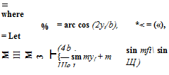
where b denotes the total span, c denotes wing chord, у = arc cos (2yfb), and Am are unknown coefficients. If we write this equation for n values of y, using the known values of b, c, a0, and a, we obtain n linear equations for Am:
 ci (C =y,
(m, і = 1, 2, • • •, я) (12)
then Eq. 11 may be written as
A’ E = a (13)
|
where A’, a’ denotes the transpose* of A and a, respectively. Hence,
|
Similar matrix representation for other methods of solving the liftingline equation can be made.4,38 In all cases, we may write the result as
![]() cC; = yga
cC; = yga
where Л is a square matrix, to be identified as ac according to Eq. 9, or as ©'(Z-1)’ according to Eq. 17.
The deflection of the control surface may be regarded as an initial twist and can be included in a(r). The equivalent angle of attack corresponding to a control-surface deflection p is
where a0 and dCjdp are the two-dimensional values of the airfoil section. Of course, Cm must be properly related to p.
Equation 4 can be represented in matrix form as follows:
![]() Fi cosЛ cSC; + (Hj cos2A – ^ sin A cosA j c2S(eC, + CMj
Fi cosЛ cSC; + (Hj cos2A – ^ sin A cosA j c2S(eC, + CMj
(21)
A similar expression for 0 is obtained by replacing Hj by F2, H2, respectively. In Eq. 21. e, sin A, cos A are diagonal matrices whose elements are, respectively, values of e, sin Л, and cos Л evaluated at the points (лі, л2, • • •, sn). S is a diagonal matrix of “weights” defined by Eq. 14 of § 3.7.
* Interchange of rows and columns.
Combining Eq. 21 with Eqs. 3, 5, and 19, we obtain сСг = Jfa. = A[a(r) + ot(e)]
![]()
![]() 3w
3w
3s
= AWT) + ?E cC, + gGc2Cm]

![]() / 8F, 3F, 1
/ 8F, 3F, 1
— I cos A ——– sin A —— I sin A cos A ceS (23)
Эо 8 a / J
/ 8F, 8F,
G = (cosAH2—sinAH1)cos2A— I cos Asin ЛI sinAcosA S
For conventional airfoils Cm depends on /3, but is independent of a. Equation 22 can be written as
(I – q№)cCt = A[*{r) + ?Gc2CJ (24)
Hence,
сСг = (I – qAE)-1 AWr) + ?Gc2CJ (25)
The lift per unit span qcCt can therefore be obtained by matrix operations. For a given value of q, the inverse (I — qAJ&T1 can be calculated by Crout’s method.
When the matrix I — qA& is singular, i. e., when the determinant |I — qAM vanishes, the inverse (I — qAEY1 does not exist. The lift distribution corresponding to a change in angle of attack <x(r) becomes indeterminate (tending to infinity). The value of q that satisfies the condition
|I – qAE| = 0 (26)
is the dynamic pressure at divergence.
An eigenvector (i. e., a column matrix) u satisfying the equation
(A$——- —-11 u = 0 (27)
‘ 7tiiv ‘
can be determined by a method of iteration as follows. Starting with an arbitrary nonvanishing vector % we compute successively the following sequence:
“o
Ui = Л&Щ
u2 = = (j№)2u0 (28) u„ = A^in-1 = (№)’
It can be shown that, if qilv is the smallest, (in absolute value), simple, real eigenvalue,*
lim —-^aiv (29)
n-*co U-п
and, aside from a numerical factor,
lim u„ – s – u (30)
П—У 00
where u is an eigenvector satisfying Eq. 27 and the ratio un_-Jun means the ratio of the corresponding elements in the column matrices and u„. Equation 29 is useful for calculating the divergence speed.
Let us choose a particular vector u0:
Uo = AWr) + *Gc*CJ (31)
Equation 25 can be written as
cC; = (I – qMY
00
= «о + ^iq£Ef% (32)
= 110 + ^% + q% u2 + ■■■ + qkuk + – ■ ■
Let m be so large that um approximates the eigenvector u with negligible error. Then, for k^m,
= G€e)4 = (-M Щ (33)
Vfdiv’
The remainder after m terms in the series on the right-hand side of Eq. 32 can be summed as follows:
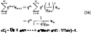 |
Therefore,
The series expansion can be justified* for q < |^dW|. The form of the
* See Ref. 3.20, §§4.14-4.17, p. 134. The existence of a real eigenvalue cannot be assured when the matrix AE is unsymmetric. For Eq. (35), see Ref. 3.20, §3.9, p. 81.
solution 35 was first given by Pines.4,30 In practical applications, it is often sufficient to take m = 2 or 3.
For certain sweptback wings, <jrdiv is negative. Physically the wing will not diverge. Yet the convergence of the series in Eq. 35 fails when q > |?divl – A method of extending the radius of convergence is discussed by Gaugh and Slap.4-29
Aileron Reversal. The rolling moment about the airplane centerline is
![]() (36)
(36)
where {;у„}’ is a row matrix with yn as elements.
If we take a(r) and CM in Eq. 25 as those corresponding to the aileron deflection /5, the solution q of the equation
![]()
 |
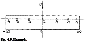
Мф.= 0 Ф Ф 0)
Using Prandtl’s lifting-line theory, find the symmetrical lift distribution corresponding to a change of angle of attack at the wing root.
Since Л = 0, only F2(s, a) and H2(s, a) are needed. For a uniform beam having a straight elastic axis, F2(s, a) = 0, and
 |
In Eq. 39, s, a are measured from the wing root. These expressions are valid for positive s, a. For the other half of the wing, the sign on the
right-hand side of Eq. 39 should be changed so that H%(s, a) remain positive.
|
* a~* (у,) (ys) (yi) 0.92388 0.70711 (у г) 0.70711 0.70711 (У.) 0.38268 0.38268 (у.) 0 0 |
 |
||
In expressing H2(s, a) in the form of a matrix, let the points of loading be уъ у2, ‘ ‘ Уп specified by Eq. 38. Then
![]()
![]() The auxiliary matrices {cos2 Л) and {ce} are diagonal matrices, this example Л and ce are constants, we have
The auxiliary matrices {cos2 Л) and {ce} are diagonal matrices, this example Л and ce are constants, we have
{cos2 Л} = cos2 ЛI = I, for Л = 0
{ce} = cel
The matrix /I is to be found by the Glauert’s method. The lift distribution
being symmetrical, only terms of odd indices in Eq. 10 differ from zero. Hence, let m = 1, 3, 5, 7:
4 b V’
![]() Ci = — / An sin тв (42)
Ci = — / An sin тв (42)
The matrix defined by Eq. 12 depends on the quantity 4b/a0c which is 4 in this example:
![]() 4 b.
4 b.
|
Its inverse is* |
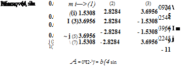 |
|
Then 2 can be easily calculated:
0. ![]()
![]() 29503 0.12520 0.04353 0.02010
29503 0.12520 0.04353 0.02010
0. 06777 0.46898 0.14736 0.03394 |
0. 01799 0.11275 0.55790 0.11970
0. 01536 0.04796 0.22120 0.54776
* Though not tabulated here, 5 significant figures were obtained for S_1 and were used for subsequent calculations.
|
||||||||||||||||||||||||||||||||||||||
|
||||||||||||||||||||||||||||||||||||||
|
||||||||||||||||||||||||||||||||||||||
 |
||||||||||||||||||||||||||||||||||||||
|
||||||||||||||||||||||||||||||||||||||
|
||||||||||||||||||||||||||||||||||||||
|
|
|||||||||||||||||||||||||||||||||||||
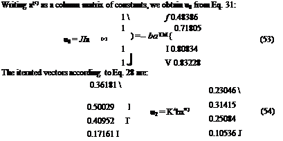 |


where
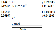
![]()
 |
|
 |
|
The ratio of the corresponding elements of the successive iterated vectors is:
Clearly the convergence of the ratios to qdiv is approximately established by n = 3, and we may take
32 GJ
qdiv= 1.598 —дг (56)
According to Eq. 35, the lift distribution across the span is given by
сСг = u0 + + q*u2 + qs "3 (57)
Using Eq. 56, and defining iq, fl2, etc. to be the column matrices given by Eq. 54 but with the factors Knba.{r) removed, we can write Eq. 57 as
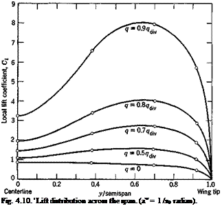
where a0 is the two-dimensional lift-curve slope which is equal to Ж = bjc in this particular example. For a few special values of the ratio qjq^, the results shown on the next page are obtained. This is plotted in Fig.
4.10 for a change of angle of attack a<r) = 1 /a0 radian.
If the wing were perfectly rigid, then H2 = E == 0, and the lift distribution is simply given by u0> This is also plotted in Fig. 4.10 as the q = 0 line.
|
?/?div |
0 |
0.5 |
0.7 |
0.8 |
0.9 |
|
C; matrix for |
0.4839 |
1.0671 |
1.8495 |
2.8289 |
5.7691 |
|
0.7180 |
1.5196 |
2.7011 |
3.9316 |
7.9551 |
|
|
a0 a(r) = 1 |
0.8083 |
1.4552 |
2.3098 |
3.3752 |
6.5675 |
|
0.8323 |
1.1037 |
1.4626 |
1.9101 |
3.2512 |
 |


