Theory
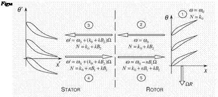
To motivate the present method, consider a stator/rotor configuration as shown in Fig. 1, where the rotor blades vibrate with a frequency и о and nodal diameter k0. When the blades vibrate, the system responds aerodynamically producing acoustical, vortical, and entropic waves that will propagate away from the rotor. Some of the upstream propagating pressure waves will impinge on the stator blades. The stator will, in turn, respond aerodynamically, which will generate new waves and travel away from the stator. Some of these waves will later impinge on the rotor blades, and the process will repeat. Because of
the relative motion of the rows, the frequency and the interblade phase angle of the waves in one row will be different when viewed in the frame of reference of the other rows, thus the initial unsteady excitation will scatter and shift into different modes.
The ‘Coupled Mode” analysis of Hall & Silkowski has demonstrated the importance of multistage coupling on the aeroelastic behavior of multistage machines. Nevertheless, without modification, the new method cannot be efficiently used for more more complex ft>w models, e. g. the two and threedimensional Euler equations. In the case where a potential fbw model is used to compute the unsteady aerodynamic refection/transmission coefficients that describe how spinning modes interact with blade rows, many of the coefficients can be computed with a single LU (lower-upper) matrix decomposition. However, the discretized time-linearized Euler equations are generally solved iteratively using pseudo time marching. Only a handful of refection/transmission coefficient can be computed using a single time-linearized calculation. Thus, the computational advantage of the original Coupled Mode analysis is somewhat diminished for complex flows.
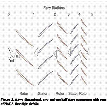
In this paper, we present an alternative approach for solving the multistage problem. To motivate this technique, suppose that the machine to be analyzed has five blade rows with B1, B2, …, B5 blades per blade row, respectively (see Fig. 1). Suppose that rows 2 and 4 are stators, whereas rows 1, 3, and 5 are rotors. Next, blade row 3 (the middle rotor) is prescribed to vibrate in a traveling wave motion with frequency ш0 and n0 nodal diameters corresponding to a fixed interblade phase angle a0. Then, between the blade rows, the unsteady ft>w will be composed of ‘"waves” with N nodal diameters, where
![]()
 |
N = no + niBi + П2В2 + П3В3 + П4В4 + П5В5
 |
and n, n2, n5 can take on all integer values. In the rotor frame of refer
ence, the temporal frequency of the waves will be
ш = шо + (П2В2 + П4В4) Q (2)
where Q is the rotational rate of the rotor. Similarly, in the stator frame of reference, the frequency is
ш = шо – (niBi + П3В3 + n5B5)Q (3)
In practice, only a few of the many possible modes, i. e. (n1,n2,…,n5) combinations, contribute significantly to the row to row coupling. This suggests the following strategy, which is the one used in this paper. For each blade row, computational grids for a single passage are generated, and the steady Euler equations are solved on these grids. Then, for the unsteady problem, multiple time-linearized solutions are solved simultaneously on each of the three grids. On each grid, several time-linearized solutions are computed, one for each frequency and interblade phase angle associated with the (n 1,n2,…,n5) modes retained in the model. At each iteration of the pseudo time-marching scheme, the unsteady solution at the boundaries between the rotor and stators are Fourier transformed in the circumferential direction to determine how much of each (n1,n2 ,…,n5) mode is present. This information is then passed
between the stator and the rotor grids allowing acoustic, vortical, and entropic waves to pass from one frame of reference to the other.
This approach has a number of advantages over a direct nonlinear time – simulation of multistage fbw. First, in the time-linearized (frequency domain) multistage fbw solver, one blade passage is required for each blade row. For a nonlinear time simulation, enough passages must be retained in each blade row so that the computational domain is periodic in the circumferential direction. So for example, a rotor/stator geometry with 22 and 30 blades can be reduced to 11 and 15 blades, but no further. Furthermore, the time-simulation must be computed time-accurately. This makes such calculations extremely expensive. Using the time-linearized approach, on the other hand, one can use local time stepping, multigrid acceleration, and other acceleration techniques commonly used in steady flow calculations,
In the present analysis, we use an explicit Lax-Wendroff scheme to compute both the steady and time-linearized unsteady ft>w solutions (Hall and Clark, 1993). In both the steady and unsteady ft>w solvers, we use local time stepping and multigrid acceleration to speed convergence. A conservative smoothing algorithm is used to capture shocks and shock impulses.


