Tip Speed
![]()

A bmb глілг tir спррН Ьріпо tn maintain fbp 1пг*я1 vplnritipc япН Hpprpacp thf* япоїм
J. x 111^11 1.VW1 Jj^VVU llVlpU tv/ AifttULllttUll tiiv IV/VUt T V&V/VkVAWU VtllV* V*WA WMt/V Vl*V tUA^AW
of attack on the retreating blade, thereby delaying the onset of blade stall for a given blade area and advance ratio. A high tip speed also gives the rotor a high level of stored rotational kinetic energy for a given radius and helps reduce design weight. Because P = £2 Q, a high tip speed reduces the rotor torque required for a given power and allows a lighter gearbox and transmission design. However, there are two important factors that work against the use of a high tip speed: compressibility effects and noise. Compressibility effects manifest as increased rotor power requirements. If the drag divergence Mach number of the tip sections is exceeded, the sectional drag (and thus rotor power) increases dramatically – see Section 5.4.3. Therefore, reducing the tip speed permits a higher flight speed to be achieved

 |
|
|
|
|
|
|

![]()
![]() Advance ratio, ц (or foward flight speed)
Advance ratio, ц (or foward flight speed)
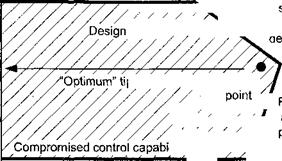
Figure 6.5 Aerodynamic, noise, and autorotative constraints imposed on the selection of rotor tip speed. Adapted from Prouty (1998) and other sources.
before compressibility effects become important. The use of a thinner airfoil at the blade tip and/or a swept tip shape can help significantly to delay the onset of compressibility effects to a higher advance ratio. Rotor noise increases rapidly with increasing tip Mach number. At low tip speeds, the noise resulting from the steady and harmonic loading on the blades is dominant. At higher tip speeds, the noise caused by blade thickness effects becomes an important contributor to the overall sound pressure, and the noise signature can become increasingly obtrusive.
Figure 6.5 shows what would be considered the range of acceptable tip speeds for conventional helicopters. The challenge for new rotor designs is to extend both the stall and compressibility limits to a higher forward flight speed. Yet, this is not easily achieved. The usual design constraints of maintaining good hover performance and acceptable autorotational characteristics (stored kinetic energy in the rotor system) severely limit the range of acceptable rotor tip speeds. However, the development of modem high-lift airfoil sections for rotors has permitted a reduction in rotor tip speed and, therefore, rotor noise levels, without compromising other aspects of the rotor performance. The use of thinner and/or “supercritical-like” airfoils and swept tips can also help alleviate compressibility effects – see Section 6.4.6. For many rotor designs, the autorotative kinetic energy limit may be an issue – see Section 5.6.3. Although this can be improved by adding rotor mass, the corresponding decrease in payload and the increase in blade and hub loads because of the higher centrifugal forces are usually unacceptable. In light of the foregoing, these issues tend to set the lowest possible allowable main rotor tip speed to about 680 ft/s (207 m/s) for a conventional helicopter.
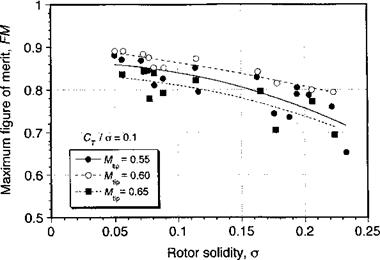
Systematic experimental measurements of rotor performance (thrust, power, figure of merit) at different operational tip speeds (or tip Mach numbers) and rotor solidities are relatively scarce. Figure 6.6 shows the effects of rotor tip Mach number on the figure of merit as a function of rotor solidity. While there is clearly scatter in the data, the results
|
Figure 6.6 Measured figure of merit variation versus rotor solidity for different main rotor tip Mach numbers. Data source: Department of the Army, Engineering Design Handbook (1974). |
confirm that operation at lower blade tip Mach numbers and lower rotor solidities is very desirable if hovering performance is to be maximized. At higher tip Mach numbers the rotor performance degrades because of the increasing compressibility losses. However, it must be recalled that rotor operation at low tip speeds will compromise forward flight performance because of the need for the retreating blade to operate at higher angles of attack and closer to the stall, all other factors being equal. In addition, the need to allow sufficient stall margin in the rotor design, especially for helicopters designed for high maneuverability and agility (see Section 5.9), requires the use of a higher main rotor tip speed.


