Wake generators
The presence of the wakes shed from an upstream blade row is simulated using a wake generator. At the Whittle laboratory, the low speed cascades, the wake generator consists of bars fitted between two belts placed on either side of the side walls. The wake generator is driven by a motor by means of mechanism of belts and pulleys and provides linear motion to the bars.
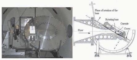
In high-speed fbws, the matching of similarity parameters demands a higher speed from the bars. For mechanical reasons this cannot be achieved with the type of bar passing wake generator typical of low speed rigs. Instead, the high speed bar wake generator consists of a number of metal bars equally spaced at the outer periphery of a disk that rotates in a plane parallel to the leading edge plane of the cascade. In this way the circumferential speed of the bars can be increased to the levels that are required in the cascade experiments. A cover encloses the rotating disk and bar assembly thus creating a sealed chamber containing the bars. This sealed cavity is needed to prevent the leakage that would occur if the cavity were opened to the plenum, i. e., to exit conditions. Low speed cascade testing tends to suffer from this sort of leakage. Therefore, controlling the inlet periodicity is easier in high speed due to the sealed chamber that contains the bars. The cover has a rectangular opening aligned with
the exit of the convergent nozzle over which the cascade is mounted. A similar configuration has successfully been used in Oxford (Doorly, 1984).
|
Figure 1. High speed rotating bar rig, frontal view (left) and cross section (right) |
The bars move across the front of the cascade, thus simulating the upstream blade row. In the high speed rotating bar rig the bars are made of hypodermic tube. They are fitted at the outer periphery of the rotating disk. When the bars cross the test section, they are subjected to a transverse aerodynamic loading. This loading defects the bars and thus limits their performance. The defection, 5, must be smaller than the distance between the bars and the cover x.
The bars are also subjected to an axial loading due to centrifugal effects. The axial tension tends to straighten the bars and thus reduces their defection. The defection is reduced, for a given diameter of the bars, by placing a weight on the tip of the bars. Additionally, when the bars leave the test section, the aerodynamic loading ceases. This transient leads to forced vibrations of the bars. By placing the weight on the tip of the bars, these vibrations are also reduced. The maximum mass that can be used is given by the maximum strength of the material.
The above discussion shows how to avoid some the mechanical constraints limiting the performance of the bars. These limitations must be taken into consideration when fixing the scale of the cascade. Only in this way can a realistic simulation of the blade-wake interaction phenomena be achieved.
1 This distance is shorter than the axial gap between the bars and the leading edges of the cascade


