Wall Transpiration model
This model places the vortex sheet on the actual body as in the Simple Inviscid Model shown in Figure 3.1. But now a source sheet of some strength A(s) is also added, as shown in Figure 3.3. This generates a fictitious wall transpiration or mass flux distribution {pV)w(s). The resulting EIF is thus intentionally not made tangent to the real body, which enables simulating the displacement effect.
![]()
|
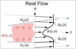
3.3.3 Wake modeling The boundary layers on a body merge together at the trailing edge or rear point and trail downstream as a wake. A wake has two edges — upper and lower — where the potential-flow quantities will now be denoted by ()u and ()i, respectively. The particular vertical location of the s-axis, or equivalently the n — 0 point, is not significant, and it can lie anywhere in or near the wake. If the wake is thin compared to the streamwise radius of curvature, then it has a nearly uniform static pressure across it like a boundary layer. Also, the lower and upper potential flows have the same freestream total pressure, so that the two edge velocities must also be the same, and so both can be denoted by ue. Pu(s) — pi(s) ^ Uu(s) — ui(s) — Ue(s) (3.12) The 2D wake has a nonzero mass defect and in general nonzero normal mass fluxes at nu and ni. Repeating the previous mass flux analysis for the wake, the real-flow edge mass flux relation (3.6) becomes a jump condition across the wake. A(pV) = pV(s, nu) – pV(s, ni) where m(s) 5*(s) Note that the m and 5* definitions are the same as for the wall case, aside from the different edge limits. Repeating the mass flux analysis for the Displacement-Body and Wall-Transpiration models, and requiring that the resulting A (pV) matches the real-flow result (3.13), gives the required displacement body thickness, and the required source sheet strength. An(s) — 5*(s) (2D-wake Displacement Body model) (3.14) 1 dm |
|
(peUe – pu) dn — peUe5* pu |
 |
|||
|
|||
|
|||
|
|||
|
|||
|
|||
|
|||
|
|||
|
|||
|
|
||
|
|||
|
|||
 |
These are the same as (3.8) and (3.11) for the boundary layer, except that An now only gives the thickness of the wake displacement body. The camber shape of the wake displacement body must be implicitly determined from the zero pressure jump or velocity jump requirement, such that the wake displacement body carries no lift.
 |
Figure 3.4: Real viscous flow of wake approximated by two EIF models which capture the wake’s displacement effect.
The EIF models resulting from the above matching relations are shown in Figure 3.4. Note that the Displacement Body model requires the use of two vortex sheets, which must have equal and opposite strengths as required by zero velocity jump requirement across the whole wake.
Yu(s) + Yi(s) = 0 (3.16)
3.3.4 Improved flow model advantages
Both the Displacement Body and the Wall Transpiration models quantitatively give very nearly the same results when incorporated into potential flow calculation methods, and both are great improvements over the Simple Inviscid model when separation is present. An example comparison is shown in Figure 3.5 for an airfoil from zero lift to beyond stall. At small lift coefficients where the displacement effects are weak, the three models give comparable results, as shown in Figure 3.6 for a = 0°. At a large lift coefficient with trailing edge separation, the differences are quite significant, as shown in Figure 3.7 for а = 16°.


