Aerodynamics of the helicopter
The purpose of this chapter is to establish methods of determining the various aerodynamic rotor forces required in the design and analysis of the helicopter. These methods are presented for all operating states of the rotor, such as hovering, powered vertical ascent and descent, forward flight, and autorotation. Initially, we consider the isolated-single rotor, and then follow with its application to different helicopter configurations.
Before we examine the aerodynamic forces to which it is subjected, we describe a typical helicopter rotor. In forward flight a rotor blade encounters
|
|
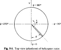
an unsteady flow, due to the forward velocity, which adds to the rotational velocity of the blade as it advances into the direction of flight and then subtracts from the rotational velocity as it retreats. This is illustrated in Fig. 5-1, which is a planform view of one blade of a rotor. Its azimuth position, denoted by ij/, is measured positively in the direction of its rotation from its downstream position.
At the tip of the blade the velocity of the air in relation to the blade is equal to (toR + V) at ф = 90° and (coR —V)aUl/ = 270°. Unless some provision were made, these unequal velocities would produce unequal lifts on either side of the helicopter and would result in an undesirable rolling movement and excessive alternating air loads on the blade. It was Juan de la Cierva who, in the early 1920’s, first applied the principle of an articulated rotor to the autogyro as a means of equalizing the lift of the advancing and retreating blade. In an articulated rotor the blade is allowed to flap up and down about a horizontal hinge close to the center of rotation of the rotor. Thus, as the blade advances and develops more lift, it begins to flap upward. This then introduces a downward vertical component of velocity in relation to the blade which reduces its angle of attack, hence the lift of the advancing blade. As it retreats, the opposite is true, for a downward flapping of the blade produces an increased lift.
In addition to being able to flap, the blade is also frequently hinged about a vertical axis near the center of rotation so that it is free to oscillate or “lead and lag” in the plane of rotation. Such a rotor is described as being fully articulated when it employs this universal action. The lead and lag motion of the blade is provided to relieve the chordwise bending moments which result from the unsteady coriolis forces produced by the flapping.
The teetering or seesaw type of rotor is another design often used for helicopters. The principle is similar to the flapping rotor except that the blades are connected rigidly to one another, and as the advancing blade flaps up the opposite, or retreating, blade must flap down.
Because the blade of the articulated rotor is free to flap, there is an upward movement of its sections about the flapping axis which is caused by the thrust that occurs even in steady hovering. In this case the blade assumes a position in which the moments about the flapping hinge due to the centrifugal force and weight of the blade exactly balance those produced by thrust. This steady deflected position of the blade from a horizontal plane is referred to as coning, whereas its oscillating movement to both sides of the steady position is called flapping.
A study of the dynamics of blade motion will show that the flapping motion lags the disturbing aerodynamic forces by 90°. Thus, because of the unbalance in the resultant velocities on the advancing and retreating sections, the blade reaches its maximum flapping angle at ф = 180° and its minimum at ф = 0°. This longitudinal flapping, fore and aft, is the result of unequal velocities between the advancing and retreating sections.
In addition to longitudinal flapping, an articulated rotor also experiences lateral flapping, which is the result of the coning that produces higher angles of attack on the blades at ф = 180° than at ф = 0°. This is best explained by reference to Fig. 5-2. It is readily seen that if /? equals the coning angle a component of the forward velocity V sin /? is going up through the blade at ф = 180°, thereby increasing the angle of attack of the blade sections at this position. However, at ф = 0° a component of equal magnitude but opposite direction is acting on the blade to decrease its angle of attack. Thus the blade has its maximum lateral flapping at ф = 270° and its minimum at іA = 90°.
The motion of lateral and longitudinal flapping caused by coning and unequal velocities is referred to as aerodynamic flapping. Thus, if no control motion is added to the blade, a blade that rotates counterclockwise, as viewed from above, would flap up in the front and on the left side (looking forward) and down in the rear and on the right side.
In order to counteract aerodynamic flapping and to direct the thrust vector of the rotor as desired, it is necessary to provide some means of controlling the angle of attack of the blade sections in their movement around the azimuth. This can be accomplished in several ways. In one method the shaft of the rotor is tilted. Suppose the shaft of a hovering
|
|
articulated rotor were suddenly tilted. Because the blade is free to flap, its angular momentum would tend to keep it in a plane perpendicular to the original shaft position. However, as it rotated in this plane about the tilted shaft, the cyclical angle of attack of the blade would produce flapping relative to the shaft until the plane of the blade was once again perpendicular to the shaft. Because the blade is coned, it would have been more precise to speak of the plane defined by the path of the tips of the blade sections. Thus it is seen that this plane called the tip-path plane, tends to be perpendicular to the shaft.
A more common method of controlling the direction of the tip-path plane is by the use of cyclic pitch. The blade pitch angle is the angle between the plane perpendicular to the rotor shaft and the chord line of a reference station on the blade. This angle, shown in Fig. 5-3c as в, is controlled by means of a swashplate mechanism as the blade moves around the azimuth. The cyclical pitch variation introduces additional blade flapping to counteract the aerodynamic flapping and to direct the thrust vector for forward propulsion or control.
The equations describing the dynamic behavior of a helicopter rotor blade are lengthy and are not given here. Instead, a relatively simple example will illustrate the essential features of the problem’s solution. Instead of a continuous rotor, consider a finite wing rotating on the end of a long “weightless, zero-thickness” rod, as shown in Fig. 5-3. The rod is long in comparison with the span of the wing so that the velocity over the wing can be assumed to be constant with respect to radius. At an azimuth position
|
|
|
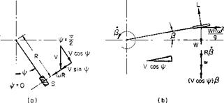
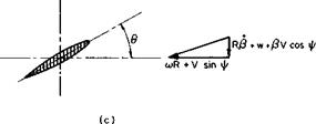
Fig. 5-3. An articulated blade: (a) planform view; (b) vertical plane containing support rod; (c) view looking in along rod. |
of ф the velocity normal to the wing is (coR + V sin ф). The component in the plane of rotation parallel to the wing span is V cos ф.
Figure 5-3b is a view in a vertical plane containing the support rod and wing. The wing is flapping up at the rate P and is instantaneously at an angle of p. At this instant the wing produces a lift L. If the weight of the wing is W, a centrifugal force, WRa)2/g will exist.
The velocities experienced by the wing are shown in Fig. 5-3b. Because of the angular velocity /?, a downward velocity of Rfi exists. Also a downward component normal to the wing equal to (V cos ф)Р exists as a result of the component of the free-stream velocity parallel to the wing.
If, relative to the plane of rotation, the wing is pitched at an angle of 9, its angle of attack will be
_ (PV cos ф + RP + w) coR + V sin ф
An assumption that the resultant velocity is approximately 10R + V sin ф leads to the following for the lift:
L = ^paS[(ajR + V sin ф)2в — (coR + V sin ф)(УР cos ф + RP + w’)],
where a is the slope of the wing lift curve and S is the wing area; p, the time rate of change of /?, can be written as
where со = ф. Hence the expression for the lift becomes
— = (1 + p sin ф)2в – (1 + p sin ф)(рР COS Ф + a аф vT)
where
L _ V
L _ $pS(coR)2’ ^ ~ aoR
If the rod is pinned so that the wing is free to flap, the sum of the moments about the hinge will produce an angular acceleration of the wing given by
W
£m = jR2p,
where W is the weight of the wing.
From Fig. 5-3c and the preceding relationships this equation can be written as
![]() g
g
co2R
We now assume that P and в have the form
P = po — a,, cos ф — sin ф — a2 cos 2ф — — в = 90 + в j cos ф + 92 sin ф.
We recall that
sin2 ф = j — j cos 2i//, cos2 Ф – j + і cos 2ф, sin ф cos ф = j sin 2ф,
and retain only constant or first harmonic terms; the differential equation in P then becomes
Po = + y)^° + 0icos^ + еійпф) + 2/i0o sin 11/ + цв2
U? Q* vv W "I <r
+ iip0cosil/ + —sin^ + ЬіСОьф — aisinij/ — — — sin^
2 Tj* rj* J w /
![]() For the above to be satisfied for all ф it follows that 1 + М2/2 a, 2ц и
For the above to be satisfied for all ф it follows that 1 + М2/2 a, 2ц и

Ol — 02 + —————- ^~7Z 0n
This simple configuration illustrates two important results of more elaborate analyses. First, notice that the displacement of the blade lags the control displacement by 90°. An increase in в1 produces a decrease in bt and an increase in 02 produces an increase in av Second, notice that, in forward flight (ц ф 0), 0O produces longitudinal flapping, whereas p0 produces lateral flapping.


