An extension to swept-winged aircraft
4.2 The considerations so far are consistent with an aircraft with unswept wings, that is, where the wings extend essentially at right angles to the direction of flight. This is an unnecessarily severe restriction: sweeping the wings backward or forward through
an angle ф (so that the main lateral axis of the wing is no longer at right angles to the flight direction, where 9 = 0 designates an unswq>t wing) leads to aircraft which still conform to Cayley’s design principles and widen the operational capabilities of the classical type to a considerable extent. The main restriction which is removed by sweep is that on top speed. As already explained in Section 2.3, the physics of compressible flows leads to a change in the type of flow when the critical Mach number is exceeded anywhere on the wing, which is bound to happen at a certain speed. This defines the intrinsic
boundary of the classical type of flow and hence of the classical type of aircraft, although we have already seen that we may go some way beyond this boundary and allow local supersonic regions without upsetting the main characteristics of the classical aircraft.
There are three distinct physical effects which are associated with sweep and which can shift the boundary of the classical type of flow to higher flight Mach numbers. These can all be explained on the basis of the concept of a swept wing of infinite aspect ratio, the infinite sheared wing (see e. g.
D Klichemann & J Weber (1953), J A Bagley (1962). A sheared wing is obtained by shearing backward (or forward) every section of an unswept aerofoil, leaving its shape and lateral position unchanged.
For an infinite sheared wing, as sketched in Fig. 4.5, we introduce a coordinate system £, n, C, which is related to the rectangular system x, y, z with x in the streanwise direction by
5 * X COS9 – у 8ІПф
n = x sinq> + у cosq> >• (4.13)
? = z.
 |
 |
The flow past a sheared wing of infinite span can be regarded as that past a
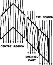
Fig. 4.5 Infinite sheared wing Fig. 4.6 Streamlines over parts of a
(left) and complete sweptback wing swept wing in planview
(right) twodimensional aerofoil put in a uniform stream with the velocity components
 (4.14)
If the flow is inviscid and if the perturbations are small, then the cylindrical sheared wing is a streamsurface with regard to the velocity component V^q along it and only the velocity components Vg and Vg are perturbed in the same manner as the components Vx and Vz in the flow past a twodimensional (unswept) aerofoil. This means that the streamlines over the sheared wing are curved in planview, as indicated in Fig. 4.6, and that there is a non-zero velocity Vq sin<p along the attachment line at the leading edge (where the two
dimensional aerofoil has its stagnation point). This kind of threedimensional effect has a profound influence on many characteristics of sheared wings.
We now compare two wings of infinite span in an incompressible flow, a thin sheared wing and an unswept wing (suffix 0) of the same streamwise section shape at the same angle of incidence in a vertical streamwise plane. Consider first the velocity increments caused by the thickness of the wings. On account of (4.13), we find that the streamwise velocity increment is reduced by a factor cos<p :
 vx “ vx0 cos1) vy = – vx0 vz = vz0
Thus the suction over part of a thick sheared wing is always smaller than that over a twodimensional aerofoil of the same thickness-to-chord ratio in the streamwise direction. Consider now the velocity increments caused by the lift on the wings. The lift on both wings can be determined from the distributions of bound vortices according to the Kutta-Joukowski theorem. The vorticity vector y(x) is inclined at an angle ir/2 – ф to the mainstream so that the pressure difference is
-Ap(x) = pVq yOO созф, (4.16)
according to (2.45). The sectional lift slope is then
CL/ae * 2ir cosp, (4.17)
bearing in mind the arguments leading to (3.27), so that the lift decreases in the ratio
Cl/CL0 = C0S(|1 (4.18)
with increasing angle of sweep. The same result can be derived from (4.14) and the linearised theory described in Section 2.2. These characteristic reductions of the perturbation velocities due to thickness and due to lift are retained even when higher-order term are taken into account (see J Weber (1972), although they take a more complex form than the simple "sweep factor" cos?.
The second sweep effect is concerned with the rate at which the perturbation velocities, or pressures, change with Mach number. We have already seen in Section 2.3 that small perturbations in compressible flows may be regarded as scaled-up, or stretched, values of those in a corresponding incompressible flow, according to the Prandtl-Glauert procedure (2.35), (2.36), and (2.37). If applied to infinite sheared wings, this procedure gives the change of the streamwise perturbation velocity with Mach number as
where Vxoi is the value of vxq for the corresponding twodimensional aerofoil in incompressible flow. Hence the pressure coefficient varies as
Cp “ ~2vx – <1 " «О2) vx2 <A-20>
according to linearised theory. We find that the perturbation velocity varies more slowly with Mach number as the angle of sweep is increased.
The third sweep effect is concerned with the mainstream Mach number at which
 |
|
local velocities or pressures reach critical conditions somewhere on the wing and thus lead to a change in the type of flow and the development of local supersonic regions. Mathematically, the equation of motion then changes from the elliptic to the hyperbolic type. For an infinite sheared wing, the motion in the Eulerian description is governed by (2.2), which can be written in the form
![]() (see R Courant А К 0 Friedrichs (1948)). This is equivalent to, _ (Эф/Э£)2 + (Эф/Эг)2 o 0 _
(see R Courant А К 0 Friedrichs (1948)). This is equivalent to, _ (Эф/Э£)2 + (Эф/Эг)2 o 0 _
 |
Now,
The criterion for critical conditions can be generalised and applied to local conditions by introducing the concepts of isobars, i. e. surfaces joining points where the pressure, or the supervelocities, are the same. On a swept wing of arbitrary shape, the isobars on the wing surface are, in general, curved»and critical conditions can be said to be reached when the local velocity component normal to the isobars, i. e. in the direction of the local pressure gradient, reaches the local velocity of sound. This is a conjecture by W G Bickley
(1946) , who stated the criterion in these terms and went further to suggest that, once the critical velocity is exceeded, a continuous steady irrotational flow is impossible and discontinuities in the form of shockwaves can be expected to occur. Bickley’s criterion has been confirmed in many experiments, but theoretical and experimental evidence has been produced in the meantime, which shows that continuous shockless compressions may also exist in twodimensional inviscid flows (see e. g. G У Nieuwland & В M Spee (1968), G Meier & W Hiller
(1968) ). These matters will be taken up again in Section 4.8.
The criterion (4.25) for critical conditions can be expressed in terms of the local velocity, the mainstream Mach number, and the isobar sweep, using (2.3) for the local velocity of sound:
 (4.26)
Alternatively, we can introduce the static pressure from (2.11) and the total head „
and obtain a critical pressure ratio
1 +ГТ1мо
 |
||
Finally, we can define a critical pressure coefficient
We note that (4.28) indicates that, the air can expand further over a swept wing than the well-known St Venant expansion which gives for the pressure ratio
 |
for у » 1.40, which applies to an unswept wing.
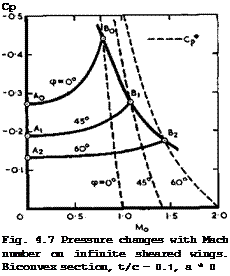
The three physical effects of sweep are illustrated in Fig. 4.7 for the simple case of a non-lifting infinite sheared wing. It can be seen very clearly how an increasing angle of sweep reduces the supervelocities at Mq * 0 (points A), how the pressure rise with Mq gets flatter, and how this process can be
LIVE GRAPH
Click here to view
The Aerodynamic Design of Aircraft
carried further until the critical pressure is reached (at point B). Thus, in principle, the mainstream Mach number of unity has no special significance for infinite sheared wings, and sweep is seen to be a powerful means for extending the speed range of the classical aircraft up to and beyond the sonic flight speed.
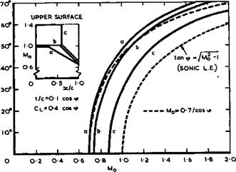
We can demonstrate the main effects of sweep again in a more practical way by considering the main design parametersi thickness-to-chord ratio t/c, lift coefficient Cl at cruise, angle of sweep q>, and flight Mach number Mq, still for the ideal case of an infinite sheared wing in a way that has first been done by J A Bagley (1961). In accordance with (4.15) and (4.18), we
|
|
Fig, 4.8 Values of angle of sweep and Mach number that correspond to three different design pressure distributions
consider a family of wings with
t/c * 0.1 cosq> and CL ■ 0.4 cos<p.
The main choice left open is then the design pressure distribution or, as in the case illustrated in Fig. 4.8, the distribution along the wing chord of the local Mach number component Mq normal to the direction of sweep. Three typical distributions have been chosen: two wholly-subcritical rooftop distributions (corresponding to RAE 101 and 104 aerofoil sections), designated (a) and (b), and one with a local supercritical region extending up to Мд s 1.4 and terminated by a shockwave at x/c =0.6, designated (c). The curves in Fig. 4.8 relate the values of the mainstream Mach number and of the angle of sweep at which these distribution are obtained over the upper surface of infinite sheared wings. We find that some sweep is needed to fly beyond about Mo = 0.7 and that the flight speed can be higher, the higher the angle of sweep. Roughly, to reach the flight Mach number of unity requires about 45° of sweep for subcritical wings and about 30° if an effective supercritical wing could be designed. To reach Mq = 1.2 (the highest Mach number at which sonic bangs at ground level are likely to be avoidable) requires about 55° sweep for subcritical wings and about 45° for supercritical wings. If one wanted to reach Mq – 2, one would have to consider wings of about 70° sweep. The simple relation
Mq = 0.7/ cosip (4.30)
gives a fair approximation of the general trend (dashed line in Fig. 4.8). In practice, there is an additional trade-off between?, t/c, and and much
depends on the actual design of the threedimensional wing. These matters will be discussed in Chapter 5.
We can now proceed to a simple first-order analysis of the performance of a family of complete aircraft. All the members of the family are considered to be classical wing-fuselage combinations and to have the same fuselage and tail – plane. They have a finite span, but we still use the relations derived for infinite sheared wings. They are designed to fly at different speeds and thus the angle of sweep of the wing is varied according to the flight Mach number (the suffix 0 denotes the unswept member of the family). This variation may follow (4.30):
M = Mq/ cos<p (4.31)
if we postulate as before that t/c “ (t/c)g cos? and C^ = C^q cos? . The wings can then be made to have the same planform area, structural depth, panel length and breadth, so that the members of this family may be thought of as one aircraft with a wing of variable sweep. The aspect ratio then decreases in proportion to cos2? :
A = Aq cos^? ; (4.32)
but the weight of the wing structure may be taken to be the same for all aircraft, to a first order. The overall weight W and the wing loading W/S are then also the same.
This family of swept aircraft has some remarkable properties. (4.31) implies that all aircraft are designed to the same aerodynamic standard and, accordingly, the values of Cpp and Ky in (3.42) may be assumed to be independent of sweep angle and speed. If we also assume that all aircraft cruise at the same value of n (which will be shown to be justified a posteriori), we find from
(4.3) that the lift-to-drag ratio at cruise is
L/D = (L/D)0(A/Aq)* = (L/D)q cos? = (L/D)0M0/M (4.33)
by (4.31) and (4.32). Thus the value of ML/D remains the same for all aircraft of this family, which implies, with L = W = constant, that the drag increases only linearly with design Mach number from one member of the family to the other: D = D0 M/Mq , (4.34) instead of increasing roughly quadratically, as one would expect for each member by itself. This remarkable fact is the reason why this family of swept aircraft is unique among all known means of transport and follows exactly the limiting line postulated by G Gabrielli & Th von Karman (1950), which has been discussed in connection with Fig. 1.6.
We note that the analysis is self-consistent in that inserting A from (4.32) into (4.5) leads again to (4.18). The latter can be written in the form
![]() ,, тЛ M
,, тЛ M
(lev )Q ^
and can conclude that this type of engine can indeed provide the thrust needed to overcome the drag given by (4.34). This shows how closely swept-winged aircraft are associated with turbojet propulsion. When A Busemann first pointed out the existence of a sweep effect in 1928, no practical application could be found because turbojet engines were not yet available. The time was ripe for successful developments of both swept wings and jet engines in 1940, when A Betz suggested the use of swept wings for the purposes described here, supported by convincing windtunnel measurements by H Ludwieg & H Strassl (1939). It then took only a few years for swept jet aircraft to fly and for H Dittmar to reach sonic speed in a Me 163 aircraft (with rocket propulsion), designed by A M Lippisch, in 1942.
![]() the members of this family must fly at different heights. The term = Po i® a function of height only, decreasing with increasing By (4.35), this varies as
the members of this family must fly at different heights. The term = Po i® a function of height only, decreasing with increasing By (4.35), this varies as
![]() (4.37)
(4.37)
so that the cruising height is increased as the cruising Mach number is increased.
We note that this implies that the Reynolds number per unit length then remains the same for all members of this family of aircraft (see J Y 6 Evans & C R Taylor (1971)).
With turbojet propulsion, we may assume that the specific fuel consumption remains constant;
according to (1.13), so that (4.38) simplifies to
WF/WF0 " R/R0 * (4*40)
using (4.36). (4.38) implies that the propulsive efficiency increases in pro
portion to the Mach number:
у V = M/Mo • (4,41)
This is reasonable to expect for turbojet propulsion because both the jet efficiency and the thermal efficiency should improve with increasing speed: the former because the excess velocity in the jet may become smaller, the latter because the ram effect may increase the pressure at which heat is added to the airstream through the engine (see also Fig. 1.1). It is then consistent to assume that the thrust increases required by (4.36) can be achieved without increasing the engine weight: this follows from (4.8), inserting from (4.18) and L/D from (4.33).
Lastly, we can determine the range andpayload fraction of this family of aircraft. The range which they reach at their respective design Mach numbers is obtained from Brdguet’s relation (1.7):
R
 With (4.41), (4*33), and (4.40), this can be rewritten as
JL . “(‘ – V“) «.*»
*° “ {‘ – "po/■ іУ
which has the solution R – Rq, independent of WFq/W. We thus find that all the aircraft of this family achieve the same range, whether they are swept or not. Sweep га primarily a means for reducing the flying time for a given range.
To a first order, the payload of all these aircraft is also the same since structure weight, engine weight, and fuel weight are the same and the weights of the systems and services may be assumed to be the same. Hence, the direct operating costs are the same, if we ignore the usually favourable effects of increased speed on the productivity or on the number of aircraft required to cope with a given volume of traffic. For this family, in this approximation, speed is obtained at no cost: one pays only for the distance, not for the speed at which one travels, – a unique advantage, which, to this extent, only aviation can offer.
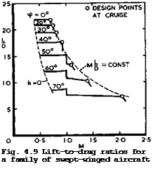 |
As will be seen below, there are many design restrictions on real aircraft, which lead to shortcomings and prevent the ideal values derived above from being achieved. The analysis presented should, therefore, be regarded as a guide and as a framework which explains what the main physical effects are and how they can be exploited and how the large number of aerodynamic, propulsive, and structural parameters hang together, to a first order. However, even the numerical values obtained are surprisingly less inaccurate than might be expected, as can be seen in a typical example for a more realistic family of transatlantic aircraft with about 150 seats in Fig. 4.9, for which the aerodynamic properties have been estimated not only as for infinite sheared wings but in more detail. The full lines in Fig. 4.9 take account of skin friction and form drag as well as of a wavedrag due to fuselage volume (shown for
LIVE GRAPH
Click here to view
The Aerodynamic Design of Aircraft
simplicity to come in at Mq * 1 instead of slightly below that) and of a wave – drag due to lift for supersonic flight Mach numbers, in addition to vortex drag, according to (3.46). The wings are assumed to be designed conservatively to have subcritical flow up to Mq * 0.7/совф, as in (4.31), and to have a steep dragrise beyond that. It can be seen that the design points at cruise lie quite close to the line MqL/D = constant = 15 of the first-order analysis. There is thus a remarkable consistency within this family of swept-winged aircraft, provided they can be designed to have the characteristics of infinite sheared wings at cruise.
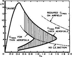
Fundamental conflicts arise when the low-speed flight conditions near the airfield are considered. On the left of Fig. 4.9 is a limiting line along which, if the present analysis is applied throughout, the flying altitude h = 0, i. e. the aircraft would hit the ground at speeds which are far too high to be acceptable for take-off or landing. A different analysis and different means for generating lift are, therefore, required to cover these conditions (see e. g. J Williams (1972) and Section 4.7). Here, we reproduce in Fig. 4.10 the
|
Fig. 4.10 Possible lift-to-drag ratios of a transport aircraft at different flight conditions (schematic) |
L/D-values which a typical transport aircraft of moderate sweep may have at cruise and also those required at take-off and landing, which correspond to Сттяу-values to be reached, for the case already shown in Fig. 4.1. Also shown in Fig. 4.10 is a shaded area within which those L/D-values may lie, which correspond to CT v-values at low speeds that might be reached by the same single aerofoil used for the cruise design. As will be discussed in Section 4.7, the actual values within this area depend on whether the aerofoil is thick and exhibits a thick-aerofoil stall or whether it is thin and exhibits a thin-aerofoil stall. In the latter case, lift is produced without a suction force at the leading edge, for a range of C^-values, We find that, whatever the wing shape, the required values of L/D and of CTtti^y are not likely to be reached by a wing which retains its geometry: some change in wing loading might bring the required and the actual curves closer together but, in principle, some high-lift devices or variable geometry will be needed to resolve this conflict. It is interesting to note that this conflict was realised very early: A M Lippisch was granted a patent on wings with variable sweep in 1942, and E von Holst flew models with various arrangements of variable sweep at about the same time.
In general terns, we may conclude that classical and swept-winged aircraft form one aerodynamic family with characteristic features which make them suitable to be flown over a network of routes of different ranges. If future developments tend to limit the flying time to about 2 hours, say, then the main application of this type of aircraft will be to short and medium ranges, up to about 3000 km if low supersonic speeds will be achieved or up to about 5000 km if it should prove possible to design an efficient swept aircraft for Mq = 2 , The potential of this type of aircraft has by no means been exploited to the full, neither in the fixed-wing nor in the variable-sweep configurations.
4.3 Classical wing theory and some extensions. Most of the properties of swept wings have been derived so far on the highly-idealised assumption of a sheared wing of infinite span, and the classical theory of unswept wings of large aspect ratio described in Section 3.2 has also been based on assumptions which are at best plausible. We need to discuss, therefore, some more rigorous approaches to the theory of threedimensional wings of large aspect ratio. This will be done in such a way that the flow models and the physical phenomena involved should come out clearly. Thus the emphasis is not so much on providing just numerical answers but on deriving approximations which have some physical meaning and give some physical insight. Whenever possible, we shall show how these approximations can be improved and numerically exact results obtained, but we shall find that some important properties, which we ought to be able to predict, cannot be calculated with reliable accuracy so that, in the end, we shall have to rely on experiments.
The theoretical approaches will, in general, be based on the method of singularities, because this will allow both twodimensional and threedimensional flows to be treated in a similar manner. The generality of a calculation method is an important aspect in this case because any restrictions on its applicability (e. g. to twodimensional flows only) may reduce the practical value of a particular method considerably. At the present stage, it is also an advantage if a method can provide a framework which allows the incorporation of empirical factors in such cases where a problem appears insoluble with the means presently available. We want to provide a balanced framework of methods, which can take account of all the effects that contribute significantly to the final answer, rather than some special method which can deal only with one or two of the effects, however accurately. What we want to try to avoid here is the imbalance of much of the work done so far in concentrating on twodimensional aerofoils and on incompressible inviscid flows, i. e. on those problems which are most amenable to a mathematical treatment.
The use of singularities implies that we shall deal separately with the effects of thickness and of lift and represent the former by suitable distributions of sources and sinks and the latter by vortex distributions. Basically, we apply the method of linearisation, as described in Section 2.2. This means that, in general, the singularities are not placed on the surface of the body but inside the body on the chordal surface.
We begin with a non-lifting, symmetrical, unswept wing in an inviscid incompressible flow. In a first approximation, the chordwise velocity distribution at any spanwise station of a wing of large aspect ratio may be regarded as the same as that over an aerofoil which extends to infinity on either side of that station. The velocity increment induced along the chord is then given by (2.25) for any given section shape z(x). For a wing of finite aspect ratio,
 |
|
The integrations in (2.25) and (4.43) can be performed explicitly for certain section shapes, such as ellipses and biconvex sections formed by parabolic arcs. For general section shapes, or when z(x) is specified only numerically, numerical solutions may be obtained by a method due to J Weber (1954) or quite readily by existing computer programs.
 |
 |
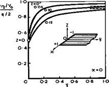
To replace the velocity increments on the wing surface by those on the chord – Ыпе is not always an adequate approximation. For example, the normal velocity component differs appreciably from qV0/2 , (2.21), near the tip of a wing. That this must be so can be seen from Fig. 4.11, which shows the velocity induced by a parallel strip of semi-infinite length normal to the mainstream and covered with a uniform distribution of sources. It will be seen
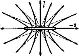
Fig. 4.11 Normal velocity induced Fig. 4.12 Streamlines of a source by a semi-infinite strip covered element of finite span
uniformly with sources
that vz/Vq is always smaller than q/2 when z ф 0 and that it falls to about half that value at the tip (y = 0). For z = 0, vz jumps discontinuously from q/2 at у > 0 to q/4 at у * 0 and to 0 for у < 0. The
reduction of vz is accompanied by the existence of a lateral velocity component vy . This can be seen from Fig. 4.12, which shows the streamlines in
a vertical plane induced by a strip of sources of finite span, and which is a
counterpart to the corresponding vortex flow in Fig. 3.2(b). The streamlines are turned outwards near the tips and the farfield is like that of a single source line at the centre, that is, like that of a body of revolution. The existence of this crossflow component adds considerably to the difficulties encountered in an analytical treatment of the flow near wing tips. The crossflow will produce a wing shape which thins down towards the tips, compared with the corresponding twodimensional aerofoil section, and which also bulges out beyond the line where the source distribution ends, again similar to a body of revolution. Thus, to produce a rectangular wing with a square tip requires a certain increase in the strength of the source distribution towards the tip. In such a flow, it is difficult to ensure that the source distribution is such as to generate a closed contour, i. e. to prevent any local inflow or outflow. This difficulty arises whether the source distributions are
placed within the wing or on its surface. The threedimensional tip effects may be localised on wings of large aspect ratio and spread inwards only about half a chord or so, but they nevertheless invalidate linearised theory in that region. The velocity increment must then be expected to lie between the full twodimensional value according to (2.25) and half that value. For a rough practical approximation, the value at the tip may be taken as about 0.7 times that from (2.25). Similar effects occur on wings of small aspect ratio in a more pronounced form. Thickness taper, whereby the wing thickness is reduced towards the wing tips, also has a distinctly beneficial threedimensional effect in that it reduces the supervelocities below the twodimensional value (see J Weber (1954) and К W Newby (1955)).
The approximation
V(x, y) = Vx(x,0) = V0 + vx(x,0)
for the velocity along the surface of the wing is also not adequate in most practical cases, especially near the attachment line along the nose of the wing. Again, it is difficult to ensure the right behaviour near the attachment line and, in particular, to prevent any local inflow or outflow, whether the sources are placed inside the wing or on its surface. A very good approximation, based on linearised theory, can be obtained by making use of the fact that the circulation around the aerofoil is zero. Thus both the line integral of the velocity along the contour and that around the sources on the chord line must be zero:
![]()

![]() dz(x)2 = 0
dz(x)2 = 0
and
V (x,0)dx = 0
If the assumption is now made that
V(x, z)ds = Vx(x,0)dx
for any elemental part of the section, we have
instead of (2.25). This relation makes the solution uniformly valid up to the leading edge. It is strictly correct for aerofoils with elliptic cross sections; it gives a good approximation for arbitrary shapes up to thickness-to – chord ratios of about 20% (see e. g. F Riegels & H Wittich (1942), F Riegels (1948) and (1961), J Weber (1953)). The "Riegels factor" in (4.44) can also be applied more generally to (4.43), as an approximation. The relations (4.43) and (4.44) can readily be extended to apply also to cambered aerofoils and to lifting and swept wings (see J Weber (1953)). Thus the thickness problem may be said to have been solved satisfactorily, except for the tip regions of a wing, which have received little attention so far and where a well-proven and reliable method has not yet been provided.
We turn now to the problem of a lifting unswept wing of high aspect ratio, again in incompressible flow. Consider first a thin wing, with the wing and
its near-planar wake represented by a vortex distribution of strength > as discussed in Section 3.2. The velocity induced by the vortex distribution at a point £ on the sheet is given by Biot-Savart’s relation
where a prime denotes a general value on the sheet. In principle, for steady flows, both the shape of the free part of the sheet and the distribution of the streamwise and bound parts of the vorticity on the wing may be determined by the three following conditions: 1 The velocity normal to the sheet is zero. This is made up of the components of v from (4.45) and of the mainstream velocity Vq.
2 Ap is zero on the free part of the sheet. This condition is obtained from (2.44) with AH – 0 , where Vs is made up of the components of v from (4.45) and of Vq in the tangential plane of the sheet.
3 The Kutta-Joukowski condition requires that Ap = 0 at the trailing edge.
The possibility of obtaining general solutions along these lines is obviously remote. The approximation introduced by F W Lanchester (1915) and by L Prandtl (1918) brings in drastic simplifications: it is assumed that both the wing
and the trailing vortex sheet lie in the plane z = 0 parallel to the mainstream, and that the induced velocity v is small in comparison with Vo. Thus the vortex model used here to obtain a more refined calculation meTKod is the same as that for the simpler method described in the Section 3.2 and does not in itself represent any improvement.
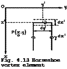 |
Thus the equations of motion are linearised. Their use can be simplified by the introduction of the so-called horseshoe vortex element, as shown in Fig. 4.13. Each element of area of the wing surface, dx’dy’ , is assumed to
contribute to the total sum of vorticity a vortex line, of strength ydx’ , which contains a bound part and then stretches to infinity downstream. The load per unit area on the wing surface due to the bound part of this element is obtained from (2.46) and is usually put in the form
*(x, y) — = ТГ – Y(x, y) . (4.46)
К °
With wing and wake made up of such elements, all the integrals derived below are then to be taken over the surface S of the wing only.
For this simplified model, the conditions described above are fulfilled automatically on the trailing vortex sheet and, for a wing of given shape z(x, y) , the linearised boundary condition on the wing reads
For simplicity, we consider only uncambered wings here, at same angle of incidence u(y) , so that
It then remains to relate the downwash vz(x, y) on the wing to the loading over its surface. With (4.45) and (4.46), the downwash at a point P(x, y,0) can be written in the form
 |
|||
which has been derived in different ways by L Prandtl (1936), E Reissner (1944) and A H Flax & H R Lawrence (1951). The latter gave the equivalent form
 |
which we prefer here since the integral involves only a Cauchy principal value; the higher-order singularity in (4.49) is more difficult to handle, although H Multhopp (1950) has defined a principal value to be taken at the singularity у = y’ . We follow here a method derived by D KUchemann & J Weber, which is described in В Thwaites (1960) (see also D KUchemann (1952)).
in the downwash equation (4.50). This clearly cannot hold for the region around у = y’ , but the error may not be serious as long as dC^/dy varies only a little. We expect, therefore, that the errors will be greatest near the wing tips, but the fact that Cl tends to zero at the tips may have a mitigating effect. However, we shall see below in Section 4.7 that the vortex model used here may be inadequate itself near the wing tips. (4.50) can then be written as
J – – L ff dx. dy. + _L f *(Х’»У> dx.
![]()
![]() 8ir Эу Jj у – у’ dx ay 4ir J x – x’ dx 8 *L
8ir Эу Jj у – у’ dx ay 4ir J x – x’ dx 8 *L
According to the boundary condition (4.48), this is a function of у only. The first integral in (4.52) is already a function of у only and hence the second integral must also be a function of у only:
. . .
This is an integral equation from which the dependence on x of the loading function £(x, y) can be determined without a knowledge of the spanwise load distribution. The function F(y) may be interpreted as being related to the downwash induced by the bound vortices, as in (3.26):
 ‘ ‘ (4.53)
*L
![]()
Cauchy’s principal value must be taken in the integral. The solution of (4.53) is
if the Kutta-Joukowski condition Л(х^,у) =0 is to be satisfied and the sectional lift coefficient
x-r(y)
cL<y> = ^7 J *(x, y)dx (4*55)
xL^y>
introduced, so that F(y) = 2C^(y). We have now derived what had only been assumed before – in (3.26) and (3.27) in Section 3.2 – namely, that flat wings of finite span but of large aspect ratio have the same ohordwise loadings as the twodimensional flat plate, at all spanwise stations. Corresponding results can be derived for cambered wings, where the series of loading functions of W Bimbaum (1923) can be introduced, of which (4.54) is the first term.
To find the spanwise loading, we insert £(x, y) from (4.54) into (4.52) and observe the boundary condition (4.48). This gives
Integrating by parts and demanding that C^(y)c(y) vanishes at the wing tips, we find
(4.56)
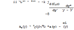 (4.57)
in accordance with (3.25). This is Prandtl’s classical aerofoil equation.
For an uncambered wing, it connects a(y), c(y), and CL(y), and it is normally regarded as an integral equation for Ci,(y). (3.34) gives the particular solution for an elliptic wing according to (3.35). The complete solution for the loading over the whole lifting surface is found by combining the spanwise loading Cx,(y) from (4.56) with the chordwise loading £(x, y) from (4.54).
The analysis can be repeated for cambered and twisted wings where a may be regarded as a function of x and у. respectively. The resulting loading £(x, y) is then again of a form similar to that of (4.54) but with the function of x replaced by that which corresponds to the chordwise loading of the twodimensional cambered aerofoil section. The spanwise loading is again determined by (4.56), where it is possible to replace a by a function of у alone; but a(y) must then be measured from the direction along which the mainstream does not produce a lift force on the twodimensional cambered section, that is, from the no-lift angle.
The solution (4.54) allows the sectional pitching moment of the uncambered wings to be determined once and for all. The pitching-moment coefficient in the direction of increasing angle of incidence, referred to the leading edge x = xL(y), is found to be
*T
![]()
![]() cm(y)
cm(y)
for each section. This gives, for the particular loading (4.54),
Cm(y) = – iCL(y) . (4.59)
Cm is negative, i. e. this is a nose-down moment. (4.59) implies that the same sectional pitching moment can be obtained from the resultant sectional lift force put at the distance of a quarter of the local chord behind the leading edge, i. e. the position of the aerodynamic centre is
xac/c = " Сш’Сь = І
at all spanwise stations.
There were numerous early attempts to solve the aerofoil equation (4.56). The first successful method, for rectangular wings, was obtained by A Betz (1919), who assumed the spanwise loading to behave like (1 – (y/s)2)J near the wing tips, which is still used in most numerical approaches. Exact solutions have been given by H Schmidt (1937), (1938) and his collaborators, while N J Musk- helishvili (1946) has treated (4.56) from a more formal mathematical standpoint. E Trefftz (1921) introduced the use of Fourier series, and this method was extensively applied by H Glauert (1926). The earlier methods have been reviewed by I Lotz (1931), A Betz (1935), and by Th von Karman & J M Burgers (1935), among others. A very successful numerical treatment was introduced by
H Multhopp (1938) (see e. g. В Thwaites, Section VIII.19, 1960). Modern numerical procedures allow solutions to be obtained in a very short time on computers. Special extensions of Multhopp’s method needed to deal with discontinuities in wing chord, or sectional lift slope, or angle of incidence have been developed by J Weissinger (1952) and J Weber (1954).
An important aspect of this derivation of the classical aerofoil theory is that it is possible to split the basic integral equation (4.50) into two equations: (4.53) for the chordwise loading, and (4.56) for the spanwise loading. Thus the loading over the whole lifting surface is obtained, and it is quite mistaken to call classical aerofoil theory a "lifting-line theory" in contrast to other "lifting-surface theories". The concept of a single lifting line on which all the bound vorticity is concentrated could be used to derive the relation for O£o » i. e. the integral in (4.56), but not the complete equation and not (4.53) either. This is an almost universally accepted mistake which originates from Prandtl (1918) himself. It has led to much confusion and to many misguided attempts at deriving improved lifting surface theories. To obtain a real improvement on classical aerofoil theory evidently requires a more accurate evaluation of the downwash equation (4.49) or (4.50), preferably on the surface of the thick wing, without invoking the assumption (4.51). What has colluded in sustaining this mistake for so long is the fact that the far – field of the flow past a twodimensional flat plate tends towards that of a line vortex at its quarter-chord point (see Fig. 3.3), and that the aerodynamic centre is located there, by (4.59).
The particular form in which the solution emerges justifies some potent concepts which were introduced in Section 3.2. We can rightly think in terms of separate contributions to the downwash from bound and from trailing vortices and hence of effective and induced angles of downwash, both of which can be regarded as constant along the wing chord, and correspondingly of effective and induced angles of incidence, ae and «j, as indicated in Fig. 4.14. The
|
Fig. 4.14 Angles and forces on a wing section |
resultant air forces(in this potential flow) is then normal to the direction inclined at the angle ae. The fact that the chordwise loading is always the same as that of the correponding twodimensional aerofoil puts all the results obtained for twodimensional aerofoils as well as those of the theory of twodimensional boundary layers at the disposal of threedimensional wing theory. Thus refinements to the thin-wing concept can be made in order to take account of wing thickness and of effects of viscosity from data for the corresponding twodimensional aerofoil. The dichotomy of classical wing theory and boundary – layer theory has dominated aircraft design for over half a century.
On this basis, methods for calculating the pressure distribution over thick twodimensional aerofoils, from an extension of (4.44) to lifting wings, or in a more general way by methods such as that by J Weber (1955), can be used to determine also the pressure distribution over threedimensional wings. The Riegels factor
1/(1 + (dz/dx)2)^
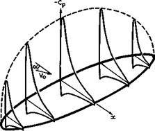
from (4.44) is then applied also to lifting wings to remove the infinite suction pressure at the leading edge which obtains in first-order theory. Fig. 4.15 gives a typical example for the pressure distribution over a flat wing of large aspect ratio.
|
Fig. 4.15 Pressure distributions over an unswept flat wing of large aspect ratio |
Within this framework, the sectional lift slope ад = Сі/ае = 2ir can be replaced by that for a thick aerofoil:
aQ = 2ir(l + t/c) . (4.60)
This is exact for elliptic sections when the Kutta condition is fulfilled at the rearmost point, and
aQ = 2ir(l + 0.8t/c) (4.61)
is a useful approximation for practical aerofoil sections with sharp trailing edge (see e. g. the example in Fig. 3.4). Correspondingly, we have for an infinite sheared wing
a = 2ir(cos<p + 0.8t/c) , (4.62)
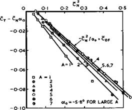
using (4.18). On the basis of Fig. 4.14, we can also expect that (3.30) for the normal and tangential forces should hold approximately for wings of high aspect ratio. Fig. 4.16 shows some results from experiments by L Prandtl &
A Betz (1920), which were designed to check the usefulness of (3.28) and (3.42) for correlating the properties of wings of different aspect ratios (in this figure, Cf is taken to be positive in the x-direction, as for a drag force, i. e. in the opposite sense as in Fig. 4.14). A series of rectangular wings of aspect ratios from 1 to 7 was tested. The wings were cambered and (3.30) must, therefore, be used in the more general form
CT–^S2 + e0®B + °DF (4*63)
(see D KUchemann (1940)), where ag is the no-lift angle of the cambered aerofoil section. The results in Fig. 4.16 show a remarkably good agreement with the prediction from classical aerofoil theory for aspect ratios between 5 and 7, which are of practical interest. Deviations become apparent only when the
aspect ratio is as low as about 3 or less, and these may be regarded as being caused by the fact that the chord is no longer small as compared with the span so that (4.51) is no longer a reasonable assumption.
To get some notion of how smatl-aspeat-ratto effects modify classical aerofoil theory, we reverse the inequality in (4.51) and assume that spanwise distances are small as compared with chordwise distances:
(У – У’)2 « (X – x’>2 . (4.64)
The downwash equation (4.50) then reads

![]()
![]()
![]()
 |
(4.65)
 |
||
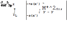
The term in square brackets has the value 2 for xT < x and is zero for Xі > x. This implies that the integration along x need be extended only from the leading edge, x s x^ , up to the plane x = constant; parts of the wing behind x* = x do not contribute to the downwash at x = x’. Hence,
where s(x) is the local semispan in the plane x = constant. The downwash is now in a form which can be manipulated further, and we refer here to the work of R T Jones (1946) on slender delta wings, from which the theory of wings of small aspect ratio originated (see also В Thwaites, Section VIII.12, I960). Some of the resulting properties which interest us here are as follows: the
load over a flat wing at an angle of incidence is
,,x”> ■ 1 <*•">
the spanwise loading is elliptic:
CL(y) = 4a |(1 – (y/s)2)* ; (4.68)
and the overall lift coefficients
CL = ітг A a, (4.69)
which is half the classical value obtained from (3.28) in the limit A -»■ 0.
The flow model we can have in mind, to give these results, is one where the concepts of bound and of streamwise vortices are be retained and where the bound vortices do not contribute to the downwash on the wing surface and the streamwise vortices provide the whole downwash:
ai= a = dK = 2aio • (4-70)
We find that this is twice the value of the downwash оцд on wings of large aspect ratio, (3.24), and equal to that in the Trefftz plane. In other words, any plane x = constant across a wing of small aspect ratio may be regarded as a Trefftz plane for the part of the wing ahead of it. Thus the general concept introduced for wings of large aspect ratio and, in particular, the angles shown in Fig. 4.14 can be used again in the case of wings of low aspect ratio; only the numerical values change. These similarities make it attractive to derive a method for determining the properties of wings of •intermediate aspect ratios, between the limiting cases of very large and very small aspect ratios, merely by interpolation, without justifying precisely which interpolation function should be chosen, provided only the behaviour at and near either limit is correctly represented. Such a method has been developed by D Ktlchemann (1952), where further details may be found.
A suitable interpolation function for the loading, which includes the limiting cases from (4.54) and (4.67), can have the form
The parameter n is then a function of the aspect ratio, still to be determined. The value n = J represents the limit A <*> and the limit n ■+■ 1 represents A 0. With this general loading, the aerodynamic centre lies at
^ – id – n) , (4.72)
which indicates the characteristic forward shift of the loading as the aspect ratio is decreased.
We retain the concepts of bound vortices and of streamwise vortices, part of which now lie on the wing, and also the corresponding downwash angles ae and 0£, with a = ae + ot£ , (4.57), as the boundary condition. But we can no longer expect that the downwash induced by the bound vortices will be constant along the chord. Therefore, we consider only its mean value over the chord, with vze formally taken from (4.53). With fc(x, y) from (4.71), this gives by integration
oe " C^(l – irn cot irn) (4.73)
and for the sectional lift slope
![]()
a – CL/oe = a
where the parameter ш is a function of the aspect ratio. The value ш = 1 represents the limit A -*■ » , and the limit ai 2 represents A -*■ 0. The variations with aspect ratio of both u and n must go sensibly together in this model of the flow and since ш = 2n in the two limiting cases, we assume
ш = 2n (4.76)
We can now fulfil the boundary condition (4.57) on the average over the wing chord and obtain the overall lift slope
 |
A suitable relation for the single interpolation function n(A) is
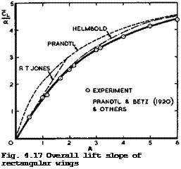
with a from (4.74). This relation has been used to calculate the overall lift slope of a series of rectangular wings, and the results in Fig. 4.17 (full line ) agree well with the experimental results of L Prandtl & A Betz (1920). This figure also demonstrates quite clearly how the actual wings interpolate between the solutions of L Prandtl (1918) and of R T Jones (1946). One is tempted to draw the general conclusion that interpolation between two good solutions is quite good enough, if suitable parameters can be found, and that heavy mathematical tools are not then needed.
 |
Properties of Classical and Swept Aircraft
![]() Fig. 4.17 also contains a curve due to H В Helmbold (1942), which is an interpolation for the total lift only, based on results for elliptic wings. This approximation agrees quite well with results by W Kinner (1937) for a circular wing and by К Krienes (1940) for elliptic wings. N Scholz (1950) obtained similar results, and F W Diederich (1951) extended Helmbold*s relation to include sweep on the basis of the concept of an infinite sheared wing. Finally, D KUchemann (1952) included sweep and compressibility on the basis of (4.19) so that _
Fig. 4.17 also contains a curve due to H В Helmbold (1942), which is an interpolation for the total lift only, based on results for elliptic wings. This approximation agrees quite well with results by W Kinner (1937) for a circular wing and by К Krienes (1940) for elliptic wings. N Scholz (1950) obtained similar results, and F W Diederich (1951) extended Helmbold*s relation to include sweep on the basis of the concept of an infinite sheared wing. Finally, D KUchemann (1952) included sweep and compressibility on the basis of (4.19) so that _
![]()
![]()

![]()
![]() (4*82)
(4*82)
This is a useful relation for quick estimation purposes. It also indicates in which preferred combinations the main parameters appear.
The methods described above for determining the properties of thick lifting wings together form a framework which can be used for many, practical purposes, including the calculation of the pressure distribution over the whole wing.
This framework is sometimes described as the RAE Standard Method. Details of the actual calculation procedure are described in an ESDU Data Memorandum (see Anon (1963) and (1973)). A consistent theory including second-order effects has been developed by J Weber (1972). There is also a very large number of other methods for calculating the loading over wings, employing a great variety of numerical techniques. In general, no new physical concepts or flow models need to be introduced, the classical model of Lanchester and Frandtl being retained, and the emphasis is on the numerical aspects. We refer here only to some od the more recent methods by H Schlichting & E Truckenbrodt (1959) and (1969), M van Dyke (1964), W Gretler (1965), P J Zandbergen et al.(1967),
H Schubert & W Wittig (1971), P Jordan (1973), H C Garner & G F Miller (1972),
H C Garner (1974), and С E Lan (1974). „
These approximate methods cannot be expected to give sufficiently reliable numerical answers in all practical cases. Therefore, the question arises of how any errors can be determined and subsequently rectified. Consider the case where the wing shape zw(x, y) is given and where first-order solutions
Next Page
q(l)(x, y) and Л^(х, у) for source and vortex distributions on the chordal plane of the wing, z = 0, are assumed to be known. We follow now a method developed by J Weber (1972) for checking and improving the accuracy of the RAE Standard Method. The singularities induce perturbation velocity components vx^, Vy(l), and vz on the surface of the wing, which, together with the components of the mainstream velocity Vq, should result in a vanishing velocity component normal to the wing surface and hence make this into a stream – surface. If the wing surface is defined by F(x, y,z) = 0, then this stream – surface condition can be written in the form
![]() V — + V — + V — =
V — + V — + V — =
x Эх у Эу z 3z
where Vx, Vy, and Vz are the components of the total velocity. With F(x, y,z) = z – г„(х, у), and restricting ourselves, for simplicity, to uncambered (but twisted) wings at an angle of incidence a(y) in symmetrical flow, we have
![]()
1 3zw(x, y) |VQ cos a + vx(x, y,zw)j + ц
V (X, y,z ) = V. sin a + V (x, y,z )
…. (4.84)
where the perturbation velocity components are used again. This is a general form, of (2.9) for threedimensional wings. If the approximate values of vx* ^, Vy 1 , and vz(l) are inserted into this relation, the error resulting from the various approximations can be determined, in principle in the form Az(x, y) of the difference between the given shape and that obtained from (4.84) when the approximate velocity components are used. This provides a valid check on the accuracy of any approximate method, and everyone who propounds a theory should feel obliged to produce such an assessment of the errors involved. So far, such checks have only been carried out on the RAE Standard Method by J Weber (1954), (1955), (1972) and J C Cooke (1958), and by В L Hewitt &
W Kellaway (1972) on their method.
An advantage of this method of checking the accuracy of approximations is that the procedure can be extended to obtain improved approximations by an itera~ tive process. In a method developed by J Weber (1972) and С C L Sells (1973) and (1974), (4.84) is used to determine not Az but Av?(x, y,zw), as the difference between the required value and that obtained by inserting the first – order approximations. By splitting Avz into a symmetrical part (arising from thickness) and an asymmetrical part (arising from lift), one can obtain corrections Aq(x, y) and A£(x, y) to the singularity distributions, using again the same approximate first-order method as before. For л(0(х, у), vortex-lattice methods, such as those by S G Hedman (1965) or by С E Lan (1974), may be used as an alternative. This leads to improved solutions
q^(x, y) = q^(x, y) + Aq(x, y) and i^(x, y) = Л^(х, у) + A£(x, y), (4.85)
and the process can be repeated. One step in this iteration is the determination of the perturbation velocity field induced by planar source and vortex distributions. This can be done to any desired accuracy by computer programs devised by J A Ledger (1972) and С C L Sells (1969). In general, the iteration converges quickly and only a few steps need to be taken.
In principle, such an iteration method may be regarded as giving numericalty_ exact answers. Strictly, to substantiate any method using singularity distri – distributions – and this includes panel or facet methods and finite-element schemes – it will be necessary to calculate the flowfield in the regions near


