CONTROL FORCE TO TRIM
One of the important handling characteristics of an airplane is the force required of the pilot to hold the elevator at the angle required for trim, and the manner in which this force varies with speed. If friction in the control system be neglected, the stick force is simply related to the elevator hinge moment. The hinge moment itself, as can be deduced from the definition of Che is roughly proportional to the square of the speed, and the cube of the airplane size. Large high-speed airplanes therefore have serious control problems, since the forces required may be too large for a human pilot to supply. Much development has gone into attempts to arrive at purely aerodynamic solutions to this difficulty. The devices employed include various forms of nose balance, and the use of geared and spring tabs. Closely balanced controls have experienced difficulties because of the sensitivity of the hinge moment to such factors as nose shape and gap, which are inevitably subject to variations in manufacture.
Another approach is to relieve the pilot of some or all of the aerodynamic load through the use of power controls. These may be designed so that the pilot supplies a fixed proportion of the control force, the power system supplying the remainder. A system of this kind is illustrated in Fig. 11.4. With such “ratio”-type controls, the feel has the same character as when power is absent, i. e. the stick forces vary with speed, and in maneuvers, in the same way. Alternatively, the power controls may be irreversible, in that none of the aerodynamic load is carried directly to the pilot. Such systems are fitted with devices that produce a synthetic feel at the stick. The stick-force characteristics can then be made virtually whatever the designer wishes. Other classes of control system provide the pilot with power amplification rather than force amplification, i. e. the power system acts so as to increase the control deflection above that which would follow from the unpowered kinematics. This has the same net effect as the ratio-type control, however, since a greater mechanical advantage can then be supplied to the pilot than would be possible without the power boost. A detailed discussion of a variety of control concepts and mechanisms is given by Kolk (ref. 6.11), to which the student is recommended.
Control-system
![]()
linkage
Pig. 6.28 Schematic diagram of an elevator control system.
 |
||
Figure 6.28 is a schematic representation of a reversible control system. The box denoted “control system linkage” represents any assemblage of levers, rods, pulleys, cables, and power-boost elements that comprise a general control system. We assume that the elements of the linkage and the structure to which it is attached are ideally rigid, so that no strain energy is stored in them. We also neglect friction, and assume that the movement of the control is slow enough that the automatic power elements have nearly zero error (e. g. the link AB in Fig. 11.4 does not rotate appreciably). The system then has one degree of freedom. P is the force applied by the pilot, (positive to the rear) s is the displacement of the hand grip, and the work done by the power boost system is Wb. Considering a small quasistatic displacement from equilibrium (i. e. no kinetic energy appears in the control system), conservation of energy gives
Now the nature of ratio or power boost controls is such that dWJds is proportional to P or He. Hence we can write
![]() Р = (ві~
Р = (ві~
ds
where 6ri = — —2 > 0, the elevator gearing (rad/ft)
 and
and
In the example of Fig. 11.4, Oj is zero in a steady state, and clearly the work done by the hydraulic system is dWb = const X J ds, where the constant derives from the various lever ratios; and J = const X He. Hence dWJd. s = const X He. The latter constant, easily found from the geometry, is G2. Finally, we write
P = GHe (6.8,3)
where G — С?! — G2. For fixed Gt, i. e. for a given movement of the control surface to result from a given displacement of the pilot’s control, then the introduction of power boost is seen to reduce G and hence P. G may be designed to be constant over the whole range of de, or it may, by the use of special linkages and power systems, be made variable in almost any desired manner.
Introduction of the hinge-moment coefficient gives the expression for P as
P = GChe8MpV2 (6-8,4)
and the variation of P with flight speed depends on both V2 and on how Ghe
varies with speed.
The value of Ghl at trim for arbitrary tab angle is given by
Che = @he о + ^fteaatrim + Metrim + (6.8,5)
From (6.7,1) we see that
Che=h(dt-d4tJ (6.8,6)
i. e. the hinge moment is zero when 6t = <5itrim as expected, and linearly proportional to the difference. From (6.7,2) then the hinge moment is
Che = M, + Cb, + (CheCr – b/Jr) -°^(h – K)CLmm (6.8,7)
where w = W/S, the “wing loading.” When (6.8,7 and 8) are substituted into (6.8,4) the result obtained is
![]()
![]() P = A + B^pV2
P = A + B^pV2
A = – G8ecew ^ (h – K)
Д
В = GSece[bA + 6’i<!o + (CheCLs – b2CLJ
|
|
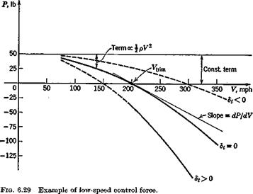
The typical parabolic variation of P with V when the aerodynamic coefficients are all constant, is shown in Fig. 6.29. The following conclusions may be drawn.


