Hypersonic Flight Vehicles and Shock Waves
Shock waves can occur if the speed in a flow field is larger than the speed of sound. Across shock waves the flow speed is drastically reduced, and density, pressure and temperature rise strongly.[53] The phenomenon is connected to the finite propagation speed of pressure disturbances, the speed of sound. At sea level this is аж « 330 m/s or « 1,200 km/h. If the vehicle is flying slower, that is with subsonic speed Ыж < 1, the pressure disturbances travel ahead of the vehicle: the air then gives gradually way to the approaching vehicle. If the vehicle flies faster than the speed of sound, with supersonic Ыж > 1 or hypersonic Ыж ^ 1, speed, the air gives way only very shortly ahead of the vehicle, and almost instantaneously, through a shock wave. In this case we speak about the (detached) bow shock, which envelopes the body at a certain distance with a generally convex shape. This bow shock moves in steady flight with the speed of the flight vehicle, i. e., it is fixed to the vehicle-reference frame, and (for steady flight) it is a steady phenomenon.
However, shock waves can also be embedded in the vehicle’s flow field, if locally supersonic flow is present. Embedded shocks may occur already in the transonic flight regime, where the free-stream speed still is subsonic, but super-critical, and in the supersonic and hypersonic flight regimes. If the shock wave lies orthogonal to the local speed direction (normal shock), we have subsonic speed behind it, if it is sufficiently oblique, the speed behind it is supersonic. We treat these phenomena in Sub-Sections 6.3.1 and 6.3.2, but refer for a deeper treatment to the literature, for instance [3]-[6].
Depending on the flight-vehicle configuration a flow field pattern with either subsonic or supersonic, or mixed, speed is resulting behind the bow
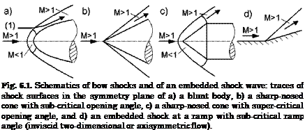 |
shock, Fig. 6.1. At a blunt-nosed body, Fig. 6.1 a), we always have a detached bow shock with a small subsonic (M < 1) pocket behind it. The flow then is expanding to supersonic speed again.
The bow shock is dissipating far downstream of the vehicle, while its inclination against the free-stream direction approaches asymptotically the free-stream Mach angle pTO. The Mach angle p reads
![]() 1
1
sm и = —. h M
It is defined in the interval 1 A M A to, Fig.
At a sharp-nosed cone, if the opening angle is small enough (sub-critical opening angle), the bow shock is attached, Fig. 6.1 b), the speed behind
it is subsonic/supersonic or supersonic, Sub-Section 6.3.2.[54] With sufficiently large opening angle (super-critical opening angle), Fig. 6.1 c), the bow shock is detached, the speed behind it is initially subsonic, and then, in the figure at the following cylinder, supersonic again.
Lastly, at the ramp we have an embedded shock wave. If the ramp angle is sub-critical, the shock will be “attached”, with supersonic speed behind the oblique shock, Fig. 6.1 d). If the ramp angle is sufficiently large (supercritical), the shock will be a “detached” normal shock, with a subsonic pocket behind it. Then the shock will bend around, like shown for the cone in Fig. 6.1 c).
The shape of the bow shock and the subsonic pocket are in principle different for RV’s and (airbreathing) CAV’s, Fig. 6.3. The slender CAV flies at small angle of attack, with a small subsonic pocket ahead of the smallbluntness nose, Fig. 6.3 a). The RV with its anyway blunt shape during re-entry flies at large angle of attack, and has a large subsonic pocket over the windward side, Fig. 6.3 b).[55]
|
Fig. 6.3. Schematic of bow shocks and subsonic pockets: traces of shock surfaces in the symmetry plane of a) a CAV (typically small angle of attack), and b) of a RV (large angle of attack), see also Section 1.2. |
Why are bow-shock shapes of interest? They are of interest because the entropy rises across them, which is equivalent to a loss of total pressure. The consequence is the wave drag, which is a another form of aerodynamic drag besides induced drag, skin-friction drag, and viscosity-induced pressure drag (form drag) [7].
The entropy rise is largest where the shock is normal to the free-stream flow (normal shock), and becomes smaller with decreasing inclination of the shock against the free-stream (oblique shock). In this respect we note two fundamentally different cases, Sub-Section 6.4.2:
1. For a symmetric body at zero angle of attack, Fig. 6.1 a), the—stagnation – point—streamline on the axis carries the largest entropy rise As, because the bow shock is orthogonal to it.
2. For an asymmetric body at angle of attack, Fig. 6.22, the streamline through the locally normal bow-shock surface carries the largest entropy rise, Aso = Asmax. The stagnation-point streamline, however, which penetrates the bow-shock surface at at a certain distance from the locally normal bow-shock surface, carries a lower entropy rise, Asi < Asmax. Hence in this case the stagnation-pressure loss is smaller than in the symmetric case.
In general it can be stated: the larger the portion of the bow-shock surface with large inclination against the free stream, the larger is at a given free – stream Mach number the wave drag.
We understand now why a RV, which actually flies a braking mission, is blunt and flies at a large angle of attack, see also [2]. In addition, as we have seen in Section 3.2, large bluntness leads to thick boundary layers, and hence to a large radiation-cooling efficiency. The blunt vehicle shape thus serves both large drag and low surface temperatures, and hence thermal loads, which passive thermal protection systems can cope with, Fig. 3.2.
The situation is different with (airbreathing) CAV’s. Such vehicles must have a low total drag, therefore they are slender, have a small nose bluntness, and fly at small angles of attack. Here the small nose bluntness has an adverse effect regarding radiation cooling. Small nose radii lead to thin boundary layers, and hence to small radiation-cooling efficiency. In CAV design tradeoffs are necessary to overcome the contradicting demands of small wave drag, and sufficient radiation-cooling efficiency.
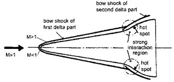
Bow-shock shapes and shock locations in general are of interest also for another reason. They can lead to shock/boundary-layer and shock/shock/ boundary-layer interactions, which we treat in Section 9.2. These “strong” interactions—locally—can cause large mechanical and thermal loads (hot spots) with possible severe consequences for the airframe integrity. They go along also with local separation and unsteadiness phenomena.
In Fig. 6.4 we show such a strong-interaction situation, which can arise at both CAV and RV wings with a second delta part, which is needed to enhance the aspect ratio of the wing in order to assure proper flight characteristics at low-speed and high-angle of attack flight.[56] Other locations where these interactions can occur, are vertical stabilizers, trim and control surfaces, inlet elements, and pylons.
|
Fig. 6.4. Schematic of strong interaction of the vehicle bow shock with an embedded bow shock at the second delta part of the wing of a CAV (seen from above) [8]. |
Finally we look at the role, which shock waves play in hypersonic airbreathing propulsion and in aerothermodynamic airframe/propulsion integration of CAV’s [9]. It is recalled that the flight-speed range of turbojet engines is up to Ыж = 3 to 4, that of ramjet engines 3 ^ M^ 6, and of scramjet engines 6 ^ M^ 12.
Important in our context is the fact that the pre-compressor Mach number of turbojet engines, like the combustion-chamber Mach number of ramjet engines is M = 0.4 to 0.6, and the combustion-chamber Mach number of scramjet engines M = 2 to 3. These numbers show that the characteristic preengine Mach numbers are much lower than the actual flight Mach numbers.
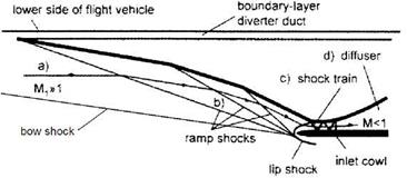
The only way to attain these engine Mach numbers is to decelerate the air stream via shock waves [9]. Normal shock waves would give too large total-pressure losses, hence one or more oblique shock waves are employed. In Fig. 6.5 we show the schematic of a three-ramp inlet, which is typical for a ramjet engine.
The inlet-onset flow a) is pre-compressed by the lower side of the forebody [2]. The forebody boundary layer must be diverted by the boundary-layer diverter, in order to avoid unwanted distortion of the inlet flow, and finally of the flow entering the engine. In the outer compression regime b) the three oblique ramp shocks, together with the vehicle’s bow shock, are centered on the lip of the inlet cowl (shock-on-lip situation at the design flight Mach number and angle of attack).
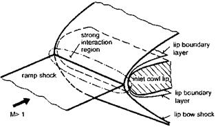
The cowl lip, which is blunt in order to withstand thermal and mechanical loads, causes an own bow shock, which interacts with the incoming shocks, Fig. 6.6. This in principle is a shock/shock/boundary-layer interaction of Edney IV type, Sub-section 9.2.2. For practical reasons usually the exact shock-on-lip situation is avoided, because of the associated adverse interaction effects [2].
|
Fig. 6.5. Schematic of a three-ramp ramjet-engine inlet. The flow is from the left to the right. Not indicated is that at the lower side due to the forebody already a pre-compression takes place. |
|
Fig. 6.6. Schematic of the shock-on-cowl-lip situation (only one incoming shock is shown) [8]. |
In Fig. 6.5 the part of the inlet is indicated, where the internal compression by a train of oblique shocks, region c), finally leads to sub-sonic flow, which is further decelerated in the diffuser d) to the above mentioned small pre-engine Mach number of the flow entering the combustion chamber.
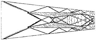
A fully oblique shock train is shown in Fig. 6.7 for a two-strut scramjet geometry at a low (off-design) flight Mach number [10]. In both the outer and in inner flow path we see shock reflections, shock intersections, Sub-Section 6.3.2, expansion waves, Sub-Section 6.5, and slip surfaces at the sharp strut trailing edges.
|
Fig. 6.7. Iso-Mach lines (and shock waves) predicted with an Euler code for a two-strut scramjet geometry at = 3 [10]. |


