Numerical Domain and Boundary Conditions
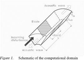
The computational domain is limited to a single vane passage by two surfaces as shown in Figure 1. There are three types of boundary conditions to be imposed. At the hub and tip radii, and vane surfaces we have solid surfaces, along which we apply the impermeability conditions, u ■ n = 0. Along
the free surfaces (upstream and downstream of vane section), we impose the quasi-periodicity conditions for the pressure and the normal velocity component, {p u • n} (x, r, §) = {pf, u • n} (x, r, 0)elcr. Here § = y – is the angular vane spacing, V is the number of stator vanes, and a = 2py" is the inter-blade phase angle. At inflow and outflow non-refecting boundary condi
|
|
tions are implemented. We seek a relationship between the values of p’ at an outgoing section, жі, to those inside the numerical domain, x2, of the form, p'(x1,r, 6) = Mp'(x2,r, 6). Here M is a mapping function. This mapping function has been developed and tested by Elhadidi, 2002.


