Numerical Results Two-Dimensional Results
In this section, the numerical results for a two-dimensional case, Configuration B (see Hall and Silkowski, 1997), will be generated using the multistage solver developed here. To simulate the two-dimensional flow, we solve a threedimensional linear cascade where there is no radial variation in the steady and the unsteady solutions.
Configuration B is composed of three rows (stator/rotor/stator) of fkt plates. The details of this configuration are given in Table 1. The axial gap between the neighboring row is 0.2 times the blade chord. For the case considered here, the steady ft>w is aligned with the airfoils, i. e., their is no turning of the ft>w. For the unsteady flow problem, the rotor blades plunge with a reduced frequency uqo/U of 1.0. The interblade phase angle of the vibration varies between – 180° and 180°. For each interblade phase angle, we compute the unsteady lift coefficient CL using the method outlined above, where
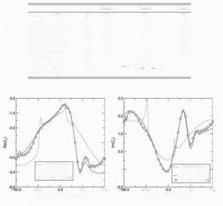
In Eq. (4), L is the total lift on the airfoil, and h0 is the amplitude of the plunging velocity. Shown in Fig. 3 is the real and imaginary parts of the computed unsteady lift when a single mode (the fundamental mode) is used for inter-row coupling. Also plotted on the same figures are the results obtained using the
|
Stator |
Rotor |
Stator |
||
|
Number of Blades |
В |
72 |
72 |
72 |
|
Chord |
c |
1.0 |
1.0 |
1.0 |
|
Gap-to-Chord Ratio |
G |
0.75 |
0.75 |
0.75 |
|
Stagger Angle |
e |
45" |
45" |
45" |
|
Relative Velocity |
U |
1.0 |
1.0 |
1.0 |
|
Relative Mach |
M |
0.7 |
0.7 |
0.7 |
|
Excitation Freq. |
Ido |
1.0 |
||
|
Excitation IBPA |
<J0 |
180" < 0 < 180" |
||
|
Rotational Speed |
QR |
0.0 |
1.414 |
0.0 |
|
Table 1. Parameters for Configuration B |

-3.0 –
Figure 3. Comparison of the real part of Cl using a single mode
two-dimensional multistage solver (CMM) developed by Hall and Silkowski, 1997. The isolated row results are obtained using Whitehead’s semi-analytical LINSUB code (see Whitehead, 1987). As one can see, the overall agreement between the CMM solver and the present solver is excellent. Furthermore, comparing the multistage analyses to the isolated blade row analysis, one sees that multistage infftences are significant, that is, the unsteady forces computed are substantially different with and without the inflience of neighboring blade rows.
Also shown in Fig. 3 is the computed lift using nine spinning modes to couple the blade rows. Note the very good agreement with one-mode solution, with only minor differences seen at interblade phase angles near ±180 °. These results, and previous results (Hall and Silkowski, 1997, Silkowski, 1996, Silkowski and Hall, 1998) imply that although multistage effects are indeed
|
Rotor |
Stator |
||
|
Number of Blades |
B |
38 |
50 |
|
Axial Chord |
c |
0.11203 |
0.12566 |
|
Radius (Tip) |
r tip |
1.0 |
1.0 |
|
Radius (Hub) |
rhub |
0.5 |
0.5 |
|
Stagger Angle(Tip) |
© |
О О |
0o |
|
Stagger Angle(Hub) |
© |
40.89o |
0o |
|
Axial Velocity |
U |
1.0 |
1.0 |
|
Axial Mach Number |
M |
0.35 |
0.35 |
|
Excitation Freq. |
w0 |
1.0 |
|
|
Excitation IBPA |
ao |
—180o < ao < 180o |
|
|
Rotational Speed |
Cl |
1.73205 |
0.0 |
|
Table 2. Parameters for Two-Row Helical Blade Configuration |
important, one can obtain accurate results to the unsteady multistage problem using as few as one spinning mode in the solution procedure. The implication is that the cost of performing accurate multistage calculation scales with the number of blade rows.


