Particular camber lines
It has been shown that quite general camber lines may be used in the theory satisfactorily and reasonable predictions of the aerofoil characteristics obtained. The reverse problem may be of more interest to the aerofoil designer who wishes to obtain the camber-line shape to produce certain desirable characteristics. The general design problem is more comprehensive than this simple statement suggests and the theory so far dealt with is capable of considerable extension involving the introduction of thickness functions to give shape to the camber line. This is outlined in Section 4.9.
4.8.1 Cubic camber lines
Starting with a desirable aerodynamic characteristic the simpler problem will be considered here. Numerous authorities* have taken a cubic equation as the general shape and evaluated the coefficients required to give the aerofoil the characteristic of a fixed centre of pressure. The resulting camber line has the reflex trailing edge which is the well-known feature of this characteristic.
Example 4.1 Find the cubic camber line that will provide zero pitching moment about the quarter chord point for a given camber.
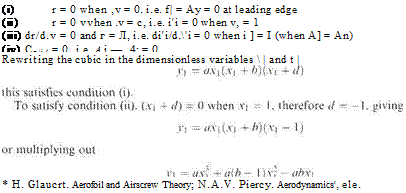
The general equation for a cubic can be written as г = a’.(x + />’)(.v + </’) with the origin at the leading edge. For convenience the new variables. V| — а/с and Vi = rT can be introduced. 6 is the camber. The conditions to be satisfied are that:
 (4.76)
(4.77)
(4.78)
Differentiating Eqn (4.78) to satisfy (iii)
![]() = 3ax +2a(b — l)xi – ab = 0 when yi = 1
= 3ax +2a(b — l)xi – ab = 0 when yi = 1
and if xq corresponds to the value of X when y = l, i. e. at the point of maximum displacement from the chord the two simultaneous equations are
|
To satisfy (iv) above, A and A2 must be found, dyi/dxi can be converted to expressions suitable for comparison with Eqn (4.35) by writing c 1 X = -(l — cost?) or *1 = -(1 — cost?) = ^a(l — 2 cos в + cos2 в) +a(b — 1) — a(b — l)cos 8 — ab = + ab — a — abj — ^a + ab — aj cos в – l-^acos2 в §+-)■ |
![]()
1 = axq + a(b — l)x% — abxo 0 = 3 ax% + 2 a(b — l)xo — ab
Comparing Eqn (4.81) and (4.35) gives
ab 3 6 96
0_ 4с + 8Яс~8с
3a S A2=Tc
Thus to satisfy (iv) above, A = A2, i. e.
![]() (a 6 36 . . , 7
(a 6 36 . . , 7
-І2 + аЬ)-Га8 c ®vmg b = ~l
The quadratic in Eqn (4.80) gives for x0 on cancelling a,
-2(b – 1) ± ф2(Ь-1)2+4хЗЬ (1 – b)± VF+T+T
Xq —————— 2—————— ————- t———-
From Eqn (4.82), b = – – gives
О
22.55 7.45
*0 = ^Г or -2Г
i. e. taking the smaller value since the larger only gives the point of reflexure near the trailing edge:
у = 6 when x = 0.31 x chord Substituting xo = 0.31 in the cubic of Eqn (4.80) gives
![]() 1
1
0.121
The camber-line equation then is
![]() У = 8.285xi ^ (xi – 1)
У = 8.285xi ^ (xi – 1)
> = 8.285^x?-yx?+|xi
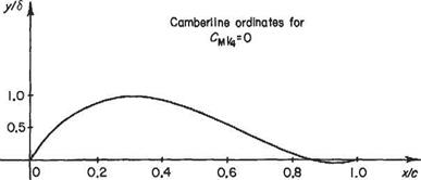
This cubic camber-line shape is shown plotted on Fig. 4.20 and the ordinates given on the inset table.
Lift coefficient The lift coefficient is given from Eqn (4.43) by
Cl = 2тг — Л0 +
 |
So with the values of Aq and A given above
giving a no-lift angle
ao = —0.518- radians c
or with /3 = the percentage camber = 1005/c
cxq = —0.3/3 degrees
The load distribution From Eqn (4.40)
, „rtf 1.04Л1 +cos0 3.125. . 3.125. „.1
k = 2U{[a———- —r-^—h———— sin 5 +——– sm20^
(V c J sin5 с c )
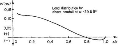
for the first three terms. This has been evaluated for the incidence a° = 29.6(5/c) and the result shown plotted and tabulated in Fig. 4.20.
It should be noted that the leading-edge value has been omitted, since it is infinite according to this theory. This is due to the term
becoming infinite at в = 0. When
a fS 5
a = – (- I = 1.048 c) c
![]() (a — Aq) becomes zero so (a — Aq)
(a — Aq) becomes zero so (a — Aq)
becomes zero. Then the intensity of circulation at the leading edge is zero and the stream flows smoothly on to the camber line at the leading edge, the leading edge being a stagnation point.
|
|
|
x/c |
0 |
0.05 |
0.1 |
0.15 |
0.2 |
0.25 |
0.3 |
0.35 |
0.4 |
0.45 |
|
y/b |
0 |
0.324 |
0.577 |
0.765 |
0.894 |
0.970 |
0.999 |
0.988 |
0.943 |
0.870 |
|
x/c |
0.5 |
0.55 |
0.6 |
0.65 |
0.7 |
0.75 |
0.8 |
0.85 |
0.9 |
0.95 |
1.0 |
|
y/S |
0.77Б |
0.666 |
0.546 |
0.424 |
0.304 |
0.194 |
0.099 |
0.026 |
0.019 |
0.03 |
0 |
|
|
|
x/c |
0 |
0.05 |
0.1 |
0.15 |
0.2 |
0.25 |
0.3 |
0.35 |
0.4 |
0.45 |
|
k/ZrrU |
CO |
0.127 |
0.123 |
0.121 |
0JI8 |
0.112 |
0.105 |
0.096 |
0.087 |
0.076 |
|
x/c |
0.5 |
0.55 |
0.6 |
0.65 |
0.7 |
0.75 |
0.8 |
0.85 |
0.9 |
0.95 |
1.0 |
|
k/tirU |
0.065 |
0.053 |
0.042 |
0JD30 |
0.019 |
0.009 |
0.006 |
5.008 |
0.013 |
0.014 |
0 |
Fig. 4.20
This is the so-called Theodorsen condition, and the appropriate Cl is the ideal, optimum, or design lift coefficient, Сюpt-


