The Entropy Layer at a Blunt Body
We have seen in Sub-Chapters 6.3.1 and 6.3.2 that in inviscid iso-energetic flow, i. e., adiabatic flow without friction and heat conduction, the entropy increases across normal and oblique shock waves. Behind these shock waves the entropy is constant again along the streamlines. If the entropy is constant also from streamline to streamline, we call this flow a homentropic flow. This situation is found in the uniform free stream ahead of a shock wave, which we have assumed for our investigations, and behind it, if the shock wave is not curved.[67] If we have flow, where the entropy is constant only along streamlines, we call this isentropic flow. This is the situation behind a curved shock wave.
We have seen also that for a given free-stream Mach number the normal shock wave leads to the largest entropy increase, eq. (6.60). Across an oblique shock the entropy increase is smaller, eq. (6.95), and actually becomes smaller and smaller with decreasing shock angle в, until the shock angle approaches the Mach angle в ^ p.
The total pressure decreases if the entropy increases:
‘Ell = e-(s2-si)/R^ (6.127)
Ptі
Hence behind a curved shock surface we get a total pressure, which changes from streamline to streamline. The lowest total pressure is found on the streamline, which has passed the locally normal shock surface. If the total pressure changes from streamline to streamline, we have, with a given pressure field, a change of the flow velocity from streamline to streamline, see Bernoulli’s equation for compressible flow, eq. (6.21): the flow behind a curved shock surface is rotational.
The law which relates the vorticity со of this rotational inviscid flow to the entropy gradient across the streamlines is Crocco’s theorem, see, e. g., [4]
|
V x rot V = — T grad s, which reads in terms of the vorticity cg = rot V |
(6.128) |
|
V x c<J = — T grad s. |
(6.129) |
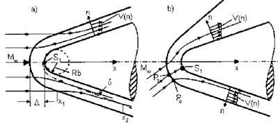
We illustrate the velocity profiles in the inviscid flow behind a curved bow-shock surface in Fig. 6.22 a) for the symmetric case, and in Fig. 6.22 b) for the asymmetric case.
|
Fig. 6.22. Schematic of the velocity profiles across streamlines due to the entropy layer in the inviscid flow field behind a curved bow-shock surface in a) the symmetric, and b) the asymmetric situation. |
In the symmetric case the profile resembles that of a slip-flow boundary layer, Fig. 9.26 on page 370. In the asymmetric case the entropy layer at the windward side has a wake-like appearance. This is due to the fact that the streamline crossing the normal portion of the bow-shock surface at P0 is not the stagnation-point streamline. That crosses the bow-shock surface at Pi. Hence the streamline crossing at P0 suffers a larger total-pressure loss or entropy rise than that crossing at Pi, which leads to the wake-like appearance.
The symmetric case is that considered usually in the literature. However, the asymmetric case appears to be that of larger importance in practice. Results of numerical investigations point to the fact that it appears at the body surface which is strongest inclined against the free stream, see the discussion in [2]. This would be the windward side of a RV-W or the lower side of the forebody of an airbreathing CAV with forebody pre-compression.
The entropy-layer effect of general interest is the so-called entropy-layer swallowing of a boundary layer. To study it, we consider the development of the boundary layer at the blunt body in the symmetrical case. We assume that the characteristic Reynolds number is so large, that we can clearly distinguish between the inviscid flow field and the boundary layer, Sub-Section 4.3.1. We assume further laminar flow throughout, and neglect the Mangler effect, [7, 29], as well as the influence of the surface temperature, which with radiation cooling decreases along the body surface very fast from its maximum value in the stagnation-point area.[68]
The boundary layer has a thickness S, which grows with increasing running length along the body surface in the downstream direction.[69] The edge of the boundary layer is not coincident with a streamline.[70] On the contrary, it is crossed by the streamlines of the inviscid flow, i. e., the boundary layer entrains, or swallows, the inviscid flow.[71]
We have indicated at the lower side of Fig. 6.22 a) the point xi on the bow-shock surface. It is the point downstream of which the bow-shock surface can be considered as straight. This means that all streamlines crossing the shock downstream of xi have the same constant entropy behind the shock surface. The streamline, which crosses the shock surface at xi, enters the boundary layer at x2. Thus the boundary layer swallows the entropy-layer of the blunt body between the stagnation point Si and the point x2. The length on the body surface between the stagnation point and x2 is called the entropy-layer swallowing distance, see, e. g., [30], in which the body bluntness via the entropy-layer swallowing can have an effect on the boundary-layer parameters.
Entropy-layer swallowing is an interesting and, for hypersonic vehicle design, potentially important phenomenon. It leads to a decrease of the boundary-layer thicknesses, and subsequently to an increase of the heat flux in the gas at the wall qgw, as well of the wall shear stress tw.[72] The changes in the characteristic boundary-layer thicknesses, i. e., of the form of the boundary – layer velocity profile, also influence the laminar-turbulent transition behavior of the boundary layer, see Section 8.2.
The effects of entropy layer swallowing have found attention quite early, see, e. g., [31, 32], however, obviously regarding only the symmetric case. In the following we consider entropy-layer swallowing from a purely qualitative and illustrative point of view.
We assume the symmetrical case of a blunt body in a given hypersonic free stream with Mach number Mand unit Reynolds number ReЦ,. In Fig. 6.22 a) we have indicated the stand-off distance A of the bow-shock surface. It is approximately a function of the normal-shock density ratio є, and the nose diameter Rs, eq. (6.122). We consider two limiting cases, assuming a comparable boundary-layer development.
1. The nose radius Rs is very large, and hence the boundary-layer thickness is very small compared to the shock stand-off distance: 6 ^ A. The boundary layer development is governed by the inviscid flow, which went through the normal-shock portion of the bow-shock surface. The entropy layer is not swallowed or only to a very small degree.
2. The nose radius Rs is small, and hence the boundary-layer thickness is not small compared to the shock stand-off distance: 6 « O(A). This situation is shown in the lower part of Fig. 6.22 a). The entropy layer is swallowed, and this means that increasingly inviscid flow with higher speed and lower temperature is entrained into the boundary layer.[73] This increases the effective local unit Reynolds number. As will be shown in Sub-Section 6.6, the unit Reynolds number directly behind the bow shock is smallest for the normal-shock part, and increases with decreasing shock angle в. This effect is directly significant for the boundary layer only away from the stagnation-point region, where the inviscid flow is weakly turned. The increased effective unit Reynolds number then increases the heat flux in the gas at the wall and the wall shear stress, as was mentioned above.
 It is clear that we can make a similar consideration assuming constant M^ and constant nose radius Rs, and a changing unit Reynolds number Re Then we observe entropy-layer swallowing with decreasing Re^, because this increases the boundary-layer thickness.
We illustrate the results found qualitatively above with results of flow – field computations made with a first-order and a second-order coupled Euler/boundary-layer method for the second case, instead with solutions for two different nose radii.
 |
|||
A first-order boundary-layer scheme takes into account only the properties of the stagnation-point streamline, and hence does not capture entropy – layer swallowing, which in reality happens. This is done only if we employ either a one-layer computation scheme, like a viscous shock-layer or a Navier – Stokes/RANS method, or a suitable two-layer computation scheme, i. e., a second-order boundary-layer method, which is coupled to an Euler method. We show results in Fig. 6.23 and Fig. 6.24 from the application of a second – order boundary-layer method with perturbation coupling, see Sub-Section 7.2.1, to the flow past a hyperbola at zero angle of attack [33], see also the symmetric case in Fig. 6.22 a).
T/W
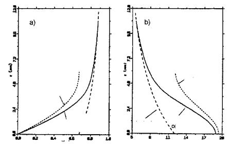
Fig. 6.23. Illustration of the effect of entropy-layer swallowing at a hyperbola [33], case 1 of Table 6.3: a) typical velocity profiles u/Vref (z) of the inviscid flow and the boundary layer without (first-order solution), and with solution) entropy- layer swallowing, b) typical temperature profiles T/Tref (z) of the inviscid flow and the boundary layer without (first-order solution), and with (second-order solution) entropy-layer swallowing, adiabatic wall situation.
In Fig. 6.23 a) we find for a given location the rotational inviscid flow profile at the wall (see also Fig. 6.22 a), upper part), and the boundary – layer velocity profiles. The boundary-layer profile found with the first-order solution, i. e., without entropy-layer swallowing, is governed by the inviscid flow at the body surface, and hence by the stagnation-point entropy. The profile found with the second-order solution blends into the inviscid flow profile at a finite distance from the surface and hence swallows the entropy – layer as the boundary layer develops from the stagnation-point region in downstream direction.
In the second-order case, i. e., the case with entropy-layer swallowing, the boundary-layer edge velocity ue/Vref is larger than in the first-order case, i. e., without entropy-layer swallowing. Consequently we have with entropy – layer swallowing a larger velocity gradient d(u/Vref)/dz|w and because of approximately the same wall temperatures, Fig. 6.23 b), and hence the same viscosity at the wall, a larger wall shear stress tw.
|
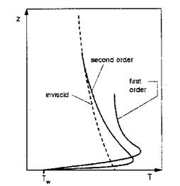
Fig. 6.24. Illustration of the effect of entropy-layer swallowing at a hyperbola [33]. Cold wall with fixed temperature Tw: typical temperature profiles T(z) of the inviscid flow and the boundary layer without (first-order solution), and with entropy-layer swallowing (second-order solution). |
Fig. 6.23 b) shows the temperature profiles for the adiabatic wall situation. In this case the adiabatic temperature Tr is a little smaller with entropy-layer swallowing than without. This is in contrast to the usually observed behavior of the wall-heat flux qgw, see also Fig. 6.24, where entropy-layer swallowing increases the heat flux at the wall. The reason for this probably is the overall
![]()
higher temperature level in the case without entropy-layer swallowing, because of the already much higher boundary-layer edge temperature Te/Tref.
A typical cold-wall case is sketched in Fig. 6.24. There indicated is the much larger temperature gradient near the body surface, where dissipation work is larger in the case with entropy-layer swallowing due to the larger velocity gradient, Fig. 6.23 a). Consequently the temperature gradient at the wall is larger than in the case without entropy-layer swallowing. With the same wall temperature Tw in both cases we then find a larger qgw with entropy-layer swallowing than without.


