Three-Dimensional Results (Torsion)
Next, we examine the effect of the number of blade rows in a multistage solution. The configuration used in the previous section is extended to seven rows (stator/rotor/stator/rotor/stator/rotor/stator). Again, the rotors are helical surfaces with zero steady pressure loading, and the stators are fht untwisted plates aligned with the axial steady fbw. The details of this configuration are given in Table 3. The axial gap between two neighboring rows is given by 0.25 x (ci + c2). The fourth row of rotor blades are assumed to pitch around the mid-chord position with a reduced frequency ш0 of 1.0 based on the local chord and the local axial velocity. The displacement of the blade is normal to the local blade chord. The amplitude of the displacement as a function of the radius is given by
a(r) = Q (r) (x — же) л/1 + Q2r2 (6)
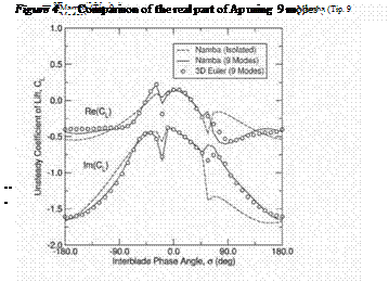
where 91 (r) is the radial distribution of the amplitude of a canti-lever beam for the first torsion mode and xe is the position of the torsion axis. In all of the solutions, the interblade phase angle is varied between —180o and 180o and the generalized force on the middle blade row is computed. Figure 6 compares solutions for the isolated rotor with a three-row and a seven-row configuration.
![]()
 |
 Surface Location, x/c
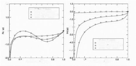
Figure 5. Comparison of CL at the midspan for coupled and isolated solutions
Note that while the forces computed using three rows are significantly different than those computed using an isolated blade row, the three and seven row results are essentially identical. This implies that the two nearest neighbors have a strong inflience on the aerodynamic response of a vibrating blade row, but more distant blade roes do not.


