Variable Pitch & Constant Speed Propellers
Back in the early days of aviation, the limitations of the fixed pitch prop soon became evident with the advent of higher – powered engines and the greater speed range of newer types
|
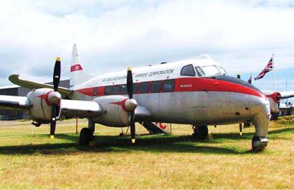
The DeHavilland Mark 1 Heron was the world s smallest airliner with four prop/engines. |
of aircraft. Since the 1930s, high performance aircraft have used either a variable pitch or more commonly, constant – speed props.
Pilots quite often incorrectly refer to constant speed props as variable pitch props. It is true, the constant speed propeller does have a variable pitch change mechanism, but there is a difference here. The variable pitch props are simply that – variable; that is, they do not have constant speed ability. Variable pitch props can be classified under three basic headings of ground adjustable, two position, or controllable props. Two different methods are employed for changing the propeller’s pitch. On the ground adjustable type, after loosening the collar bolts on the round shank at the blade root, the blade angle is then adjusted to the required pitch; the bolts are then re-tightened on the collar. The second method is more convenient for the pilot, the pitch being adjusted by a control in the cockpit while in flight. The fine (or flat) pitch position is selected for take-off and climb. On reaching cruise altitude, the pitch control lever is moved to select coarse pitch. The controllable pitch propeller works on the same principle as the two-position prop but with the addition of a number of intermediate pitch positions available for selection between the fine and coarse pitch stops. Because a given pitch is selected at any one time, the engine RPM will vary in the same manner as a fixed pitch prop with changing air speed, power settings and prop loading. It is important to remember, a VP prop does not have a constant speed unit (CSU) and therefore will not maintain a constant RPM The types of VP props mentioned above are the most common types but, there have also been other less popular, or should I say, novel types?
|
The Lockheed (L-1049) Constellation was the last of the piston/prop airliners to be built. It has four Wright R-3350 radial engines of 2200 BHP each, driving Hamilton Standard or Curtiss Electric constant-speed propellers. This aircraft is located in the Pima Air & Space Museum, Tucson, Arizona. |
In 1934, a D. H. 88 Comet won the London to Melbourne air race. The two, 230 BHP engines powered two-blade VP French Ratier props. The Ratier’s unusual feature was their method of changing the blade angle. This was achieved by pressurising the pitch change mechanism cylinder with a bicycle pump to turn the blades to fine/flat pitch for take-off and climb. As the air speed increased, dynamic air pressure acting on a disc on the front of the prop spinner overcame the cylinder’s internal compressed air pressure and turned the blades to coarse pitch; and there they stayed for the remainder of the flight. There was no way to alter the pitch while airborne and the landing (and go-around if necessary) was flown with coarse pitch After landing, the cylinder was re-charged ready for the next flight.
|
Diagram 7, VP & Constant Speed Props |
There are a few aircraft in production today using variable pitch propellers. For this author, the Denny Kitfox and the Burkhart G109 Grob motor glider are two names that come to mind, however there are several homebuilt and ultralight aircraft that use VP propellers. The original Kitfox used a three – blade, wooden, ground adjustable variable pitch propeller. The
Grob has a two-blade, VP prop with a choice of three different pitch settings of fine, coarse and feathered. The feathered position is selected after the engine is shut down at altitude and the aircraft is flown as a glider, with the fine and coarse pitch settings being used in the normal manner for take-off and climb
The idea of having a selection of pitch settings on the VP prop was soon refined to produce the constant speed prop so widely used today, made possible by the invention of the constant speed unit (CSU) located at the prop hub, which may or may not be covered by a prop spinner. The CSU will be covered in greater detail later in this book
A diagram for a VP prop would show just two curves, for fine and coarse pitch only, as opposed to a diagram for a constant speed prop, which has an infinite number of curves. Refer to Diagram 7, VP & Constant Speed Props, which shows the fine
|
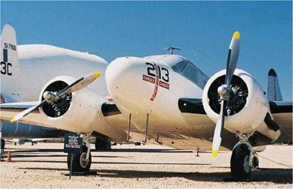
The Beech UC-45J Navigator has a pair of Hamilton Standard variable – pitch props each powered by a P&W Wasp 450 BHP engine. The Pima Air & Space Museum in Tucson, Arizona is home to this aircraft. |
and coarse pitch performance curves for a VP propeller, which also represent the fine and coarse pitch limits for the constant speed prop with an infinite number of performance curves for the constant speed envelope. The dashed line along the top of the curves indicates the infinite performance curves and efficiency over the constant speed range. Apart from an overall increase in efficiency, the constant speed propeller has several other advantages over the fixed-pitch prop. Obviously, the RPM remains constant, hence the name, along with constant power for a given manifold/RPM setting. Also, decreasing air density with altitude is compensated for by an automatic increase in propeller pitch by the CSU.
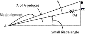 |
8A, Fine pitch
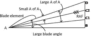 |
8B, Coarse pitch
Diagram 8, Fine & Coarse Pitch
Diagram 8, Fine & Coarse Pitch, shows the advantages and disadvantages for using fine and coarse pitch for take-off and cruising respectively. Diagram 8A, shows the condition with fine/flat pitch selected for take-off, the usual setting. The small blade angle AB-AD and the resulting small angle of attack (AC2-AD) gives the thrust and efficiency required to provide the maximum acceleration to reduce the take-off run and to produce the maximum rate of climb. As the aircraft accelerates to cruise speed after levelling off at cruise altitude, the relative air flow line (A-C2) will ‘rise’ towards the extended chord line (A-D) as the advance per rev increases, in effect, increasing the length of the advance per rev line (B-C2). This results in a reduction in the angle of attack and therefore, a reduction in thrust and efficiency. This proves the necessity to increase the prop pitch to a coarse setting for cruise flight.
In Diagram 8B, Fine & Coarse Pitch, coarse pitch has been selected for take-off, which should never be used, by choice. The large blade angle (AB-AD) with its associated large angle of attack (AC1-AD) could possibly result in stalled propeller blades giving considerably reduced thrust and poor acceleration on take-off. Assume now, the correct setting of coarse pitch has been selected for the cruising speed. Due to the large blade angle (AB-AD) the advance per rev (B – C2) and the reduced angle of attack (AC2-AD) will be at the optimum angle of attack of about three degrees providing good efficiency.
The prop control is set to full fine/flat pitch for take-off and landing but for the remainder of the flight, the pilot selects a chosen engine RPM, not pitch. The constant speed unit to maintain a constant engine RPM is constantly adjusting the prop blade angle. If the manifold pressure is increased, the CSU will increase the blade angle automatically to absorb more engine power without any increase in RPM. Even with full fine/flat pitch set for take-off, the CSU will turn the blades
|
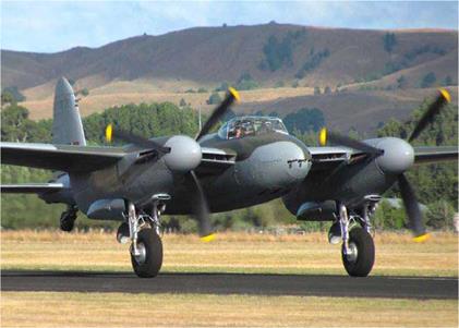
A DeHavilland DH.98 Mosquito on take-off with both props in fine/ flat pitch. This is the World’s only airworthy Mosquito in 2014. |
to a slightly coarser pitch setting to prevent over speeding as the prop load is reduced with increasing take-off speed.
The prop will only ‘constant speed’ between its fine and coarse pitch limit stops. Below a pre-determined RPM, usually around 1500-1600 RPM on light aircraft piston-engines, the prop blades will reach their fine/flat pitch limit stop and RPM will vary the same as on a fixed pitch propeller with changing aerodynamic loads, air speed and power settings. This will occur for example during the approach to land with the throttle partly closed. The fine/flat pitch limit stop provides the optimum angle of attack for low speed operations, such as during take-off and landing. Some turboprop aircraft have a ‘ground fine/flat pitch’ setting; this is an ultra-fine/flat pitch setting with an angle of attack less than fine/flat pitch for ground operations only. It produces zero thrust while taxiing and saves on brake wear. The additional blade drag will reduce the landing roll distance for an aborted take-off. The use of ground fine/flat pitch is known as ‘discing’.
If the aircraft is placed into a steep descent, the constant speed unit will turn the blades towards coarse pitch to maintain the selected RPM. However, once the blades reach the coarse pitch limit stop, the RPM will increase along with increasing air speed; the prop is driven partly by the force of the air flow through the prop disc. The coarse pitch stop is there to prevent the prop blades moving in to an over-coarse pitch setting and prevent the propeller from over-speeding. When ‘feathering’ the propeller, the coarse pitch stop is removed, but more on feathering shortly.
The variable pitch range of a constant speed propeller will spread the design speed over a greater range of speeds, as opposed to only one air speed for a fixed pitch propeller. For either the fixed pitch or constant speed prop, the blade twist can only be suitable for one speed – the design air speed. At any other speed, off-point losses will occur but will be less for the constant speed propeller.
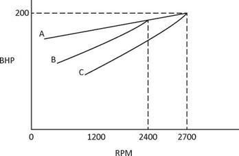
Diagram 9, Prop Load Curve, clarifies the point made above and in the previous section on fixed pitch propellers. Curve ‘A’ is the full throttle curve and represents the maximum power available from the engine at any given RPM. Curve ‘C’ represents the power absorbed by the propeller in fine/flat pitch; in this example, it produces the 200 BHP available at full revs (2700 RPM) indicated where the curves ‘A’ and ‘C’ coincide. Curve ‘B’ represents the power absorbed by the prop in coarse pitch. Full throttle is achieved before maximum RPM or maximum BHP is reached. This is usually the situation for a fixed pitch prop; on opening the throttle fully for take-off, the RPM peaks at around 2400 RPM until the aircraft’s forward speed increases and then the RPM will gradually increase to its maximum value. Some pilots refer to fine/flat pitch as flat pitch (common terminology in the USA). Same thing – different name
|
|
Diagram 9, Prop Load Curve
Larger aircraft have the range of pitch change operation increased to include reverse thrust. The pitch range around the fine/flat pitch setting through reverse pitch is referred to as the ‘Beta range’. The use of reverse pitch is known as Beta mode, and when selected, the normal operation of the constant speed unit is de-activated and the pilot has direct control over the propeller pitch (via the throttle levers) to control reverse thrust for landing roll braking. This will be covered in greater detail later in the section on Propeller Operation.


