AERODYNAMIC FORCES AND MOMENT ON A THIN AIRFOIL
For a given airfoil geometry, the mean camberline tjc(x) is a known function and the coefficients A0, Au A2,. . . can be computed by Eq. (5.51) and Eq.
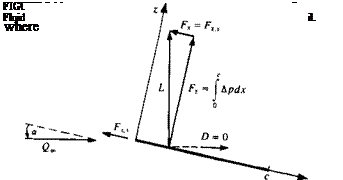
(5.52) . The pressure difference across the thin lifting surface Ap(x) can be calculated by Eq. (5.43) and the aerodynamic coefficients can be evaluated. These aerodynamic coefficieits are usaally defined in the frec-stre im coordinate system such that the lift is normal and the dlag force is parallel to the free-stream flow. In order to determine the aerodynamic lift and drag, consider the simple case shown in Fig. 5.11. The pressure difference can be evaluated by using Eq. (5.43):
Др(дг) = pG«y(x)
and since a is small is used instead of Qa cos a. The normal force Fz is then
 (5.54)
Also, the flat plate of Fig. 5.11 is very thin and the x component of the force is zero:
Fx = 0
Based on this formulation, the lift and drag forces become
L = FZ D = Fza
On the other hand, the Kutta-Joukowski theorem in Section 3.11 clearly states that the lift is perpendicular to the free-stream Q„. Thus, the aerodynamic lift is
![]() L = pQS
L = pQS
and the aerodynamic drag is
![]() (5.56)
(5.56)
Therefore, an additional force must exist in order to balance these two calculations. This force is called the leading edge suction force Fx s, and is a result of the very high suction forces acting at the leading edge (where q -* » and the local leading edge radius is approaching zero). The strength of this leading edge suction force is calculated in Section 6.5.2 using the exact solution near the leading edge of the flat plate (which is similar to the treatment of this problem by Lighthill5 4) and for the small angle of attack case is:
![]()
 |
Fxs=-pQSa
This force cancels the drag component of the thin lifting airfoil obtained by integrating the pressure difference, so that the two-dimensional drag becomes zero. This result that the aerodynamic drag in two-dimensional inviscid
incompressible flow is zero was obtained in 1744 by the French mathematician d’Alembert and hence known as d’Alembert’s Paradox. Exact solutions and numerical computations of the thick airfoil problem (where the velocity at the leading edge is finite) will verify this result in the following chapters.
To evaluate the lift of the thin airfoil, the circulation of Eq. (5.54) is calculated
T=f y(x)dx= y(0)^sin0d0 Jo Jo l
„ _ г Г 1 + cos 0 A 1c
= 2Qo= A0 —:—-—h 2 A„ sin (n0) – sin 0 dd
Jo L sin 0 n=1 J 2
Recalling that
[ (1 + cos 0) dd = я Jo
and that the integral of sin пв sin 0 is nonzero only if n = 1,
Г ■ a • a JO 1*4 when n –
I sinn0sin 0d0 = I )
Jo VO when пФ 1/
the circulation becomes
![]()
![]() Г = Є»ся(Ло + ^)
Г = Є»ся(Ло + ^)
The lift per unit span is obtained from Eq. (5.55) and is
This equation indicates that only the first two terms of the circulation (shown in Fig. 5.10) will have an effect on the lift and the integration over the airfoil of the higher-order terms will cancel out. The pitching moment about the у axis is positive for a clockwise rotation; therefore, a minus sign needs to be included when calculating the moment Af0 relative to the airfoil’s leading edge
M0= — ( Apxdx = pQaof y(0)~(1 — cos 0)^sin 0dd Jo Jo 2 2
= —-Г + —J y(0) sin 0 cos 0 dd j
After some trigonometric manipulations this results in
![]() , . c w C2 ,/ ЛЛ
, . c w C2 ,/ ЛЛ
Mo 2L + + A2-J
and by substituting the results for the lift:
![]() Mo = – pQln j(a0 + At – yJ
Mo = – pQln j(a0 + At – yJ
The moment M along the x axis can be described in terms of the lift and the moment at the leading edge as
M = M0 + x • Fz = M0 + x • L
The center of pressure xcp is defined as the point where the moment is zero (this can be considered to be the point where the resultant lift force acts):
 |
|
M = M0 + xcp • L = 0
An observation of the coefficients of the circulation (Eqs. (5.51) and
(5.52) ) reveals that only the first term A0 is a function of angle of attack a. Substituting A0 into the lift coefficient equation yields
![]()
![]() (5.65)
(5.65)
Also, for a flat plate dr]c/dx = 0 and thus all terms, except 2ла, in Eq. (5.65) will vanish. Therefore, the terms including the effect of the camberline r)c are independent of angle of attack and are a constant for a particular chordline shape. This allows us to write the lift coefficient as
С, = 2к(ос – аи) (5.66)
where ais called the zero-lift angle and is a function of the camber. Substituting the value of At from Eq. (5.52) yields
![]()
By using the Bt coefficients of Eq. (5.50a) the lift coefficient becomes
С, = 2л(а – B0 + y) (5.62a)
Comparing with Eq. (5.66) indicates that the zero-lift angle can readily be obtained as
*L„ = So-y (5.67 a)
The lift slope can be defined as
dC
C, ‘ = 2л (5.68)
* да v ‘
Equations (5.66-5.68) show that the lift slope of a two-dimensional airfoil is 2л, and that the camber will have an effect similar to an angle of attack increment Дог, but will not change the lift slope.
Next, the pitching moment coefficient (Eq. (5.64)) can be rewritten, using the formula for the lift coefficient (Eq. (5.62)), thus
Cmo=-^ + ^(A2-A1) (5.69)
Since the coefficients Alt A2 are independent of angle of attack, only the first term in this equation depends on a. Therefore, if the moments are calculated relative to the airfoil quarter-chord point the first term in this equation disappears and the moment at this point becomes independent of angle of attack. This point is called the aerodynamic center xac and according to thin airfoil theory it is located at the quarter chord. Consequently the pitching moment measured at this point is only due to the second term in Eq. (5.69):
СтсМ = ^(Л2-Л0 (5.70)
The use of this formulation for some simple chord-line shapes is demonstrated in the following examples.
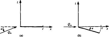
Example 1: Flat plate. As a first example, consider the thin, lifting model of a symmetric airfoil that is represented by a flat plate (shown in Fig. 5.12a). For this particular case there is no camber and rjc(x) = 0. Consequently, all terms having derivatives of the camberline will vanish, and the circulation coefficients become
A0= a A1=A2=— = 0 (5.71)
The circulation Г for the flat plate airfoil is then
Г = Q^xca (5.72)
and the lift and moment are obtained by substituting Eq. (5.71) into Eqs. (5.59)
![AERODYNAMIC FORCES AND MOMENT ON A THIN AIRFOIL Подпись: FIGURE 5.12 Free-stream and body coordinate systems for a flat plate at an angle of attack, and (5.60): L = pQS = pQlnca (5.73] Mo= -pQin—a 4 (5-74] The lift and pitching moment coefficients are C, = 2 ла (5.75) Cm — — — oc (5.76)](/img/3130/image495_3.gif) |
and the lift slope is again 2л as was shown in Eq. (5.66). The center of pressure ii at
![]()
 |
%cp 1
c Ci 4
Thus, for the symmetric thin airfoil, the center of pressure and the aerodynamic center are located at the quarter-chord location.
Because of the transfer of the boundary condition to the z = 0 plane, the airfoil trailing or leading edge can be at a certain small distance from this plane (as long as tj(x)« c). As an example, let’s solve this problem in the free-stream coordinate system, as shown in Fig. 5.126. In this case the free-stream angle of attack is zero, but the chord can be expressed as
Substituting this into Eqs. (5.51) and (5.52) yields
Aa = a and Aj = A2 = ■ • ■ — 0
which is the same result as in Eq. (5.71). Thus both methods will lead to the same results.
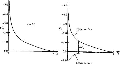
For the symmetrical airfoil, the pressure coefficient difference ДCp can be found from Eq. (5.44u) by substituting A0 and the corresponding circulation
![]()
|
In terms of x (with Eq. (5.45)) this becomes
The result of this formulation is presented in Fig. 5.13a. In Fig. 5.13ft a comparison is made with the results of a more accurate method (e. g., panel method) for a NACA 0012 symmetric airfoil. This indicates that the pressure difference is closely predicted over most of the airfoil. Near the leading edge, however, the flat plate solution is singular and the model is not accurate there.
Example 2: Thin airfoil with a parabolic camber. As an example for a simple nonsymmetric chordline shape consider the parabolic camberline shown in Fig. 5.14, with є being its maximum height. The equation of the camberline is then
*lc(x) = 4f“ [l “ “j (5.80)
Z і к
П(а)
(5.81)
![]()
![]()
Expressing this term by using the transformation x = (c/2)(l – cos в) results in
The coefficients Л„ can be found by substituting this into Eqs (5.51) and (5.52). Because of the orthogonal nature of the integral Jj cos пв cos тв d6 all terms where m Ф n will vanish. So in this case, when m = 1
An = a – 0
and only the first additional coefficient will be nonzero:
A,=4- A2 = А->= ■ ■ ■ A„ =0 c
This result can be found immediately by comparing Eq. (5.50a) with the, camberline slope
^ ^ ^ fl„ cos (пв) = 4-cos в
dx л=o £
Therefore, clearly Bx = 4e/c and the other B„ coefficients are zero.
The lift and the moment of the parabolic camber airfoil can be obtained by substituting these results into Eqs. (5.59) and (5.60):
|
L = pQljic(^a + 2 |
(5.83) |
|
M0= ~pQln^[a + 4^j |
(5.84) |
and the corresponding aerodynamic coefficients are
C, = 2jr(a + 2^ (5.85)
C.* =-§(« + 4^) (5.86)
When comparing this result for the lift with Eq. (5.66) the zero-lift angle is found to be
<^=-2- (5.87)
c
This means that this airfoil will have zero lift when it is pitched to a negative angle of attack with a magnitude of 2e/c.
The center of pressure is obtained by dividing the moment by the lift
![]() e
e
(5.88)
Note that at a = 0 the center of pressure is at the midchord and as the angle of attack increases it moves toward the quarter chord.
Also, in this case the pitching moment about the aerodynamic center can be calculated using Eq. (5.70):
 (5.89)
which indicates that the portion of the moment that is independent of the angle of attack increases with increased curvature (as e/c increases) of the camberline.
Example 3: Flapped airfoil. One of the most frequently used control devices is the trailing-edge flap. The reason for mounting such a device at the trailing edge can be observed by examining the (cos 0-1) term in Eq. (5.67). This implies that the zero-lift angle is most influenced by the trailing-edge region where 0—* therefore, relatively small deflections of the flap at the trailing edge will have noticeable effect.
To demonstrate the effect of the trailing-edge flap consider the following simple example. Here the main airfoil plane is placed on the x axis, and at a chordwise position к – c the flap is deflected by bf, as shown in Fig. 5.15. The trailing edge of the deflected airfoil is now not on the x axis but owing to the small disturbance approximation of the boundary condition the error due to the use of this coordinate system is within the accuracy of thin airfoil theory. It is assumed that the airfoil is continuous, and there is no gap at the flap hinge point. The slope of the camberline, for the case shown in the figure, is

![]() FIGURE 5.15
FIGURE 5.15
Thin flapped airfoil (without a gap at point к • c).
range 0k —* я, resulting in
 |
і ся 3
A0 = a + ~ dfd6 = a + -(n-6k) (5.91вИ
я ]вк я
An=–f Sf cosnOdO = —^-^ (5.91b)
Я )вк я n
By substituting the values of the first three A„ coefficients into Eqs. (5.62) and (5.64) the lift and pitching moment coefficients are obtained:
By setting a = 0 the incremental effect of the flap is obtained:
AC, = [2(я – вк) + 2 sin вк]6, (5.94)
ACmo = – j[(jr – вк) + 2 sin вк – sin 2ek6f (5.95)
The increment in the moment at the aerodynamic center, c/4, due to the flap deflection, is obtained using Eq. (5.70) as
AC„clk = Ц sin 2вк-{ sin ek]df (5.96)


