Aerodynamics Forces—Lift and Drag
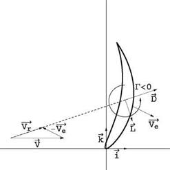
The aerodynamic forces acting on an obstacle are decomposed into lift and drag components, F = D + L, the drag being a force aligned with the incoming velocity as seen by the body and the lift being a force perpendicular to it. This decomposition is made in a frame of reference attached to the blade element, as pertinent to a moving machine. This is depicted in Fig. 10.2. The wind velocity V, and the velocity of the element V e in the absolute frame give the velocity of the fluid relative to the obstacle as
Vr = V – Ve (10.1)
The drag is aligned and in the direction of ~Vr. The lift is rotated 90° opposite the circulation Г developed inside the profile (Fig. 10.1).
Some wind machines are drag-driven, such as the Savonius wind turbine, whereas some are lift-driven as the Darrieus and the wind-axis turbines. The drag-driven machines are less efficient as the velocity of the device is always less than the wind velocity. Such systems are more useful as propulsive than power producing systems. The 15th century galleon such as Columbus “Santa Maria” belongs to the category of drag-driven systems. The modern racing sail boats use their sails as aircraft wings and are examples of lift-driven systems. A drag-driven device rotating about the y-axis (into the paper in Fig. 10.2) will correspond to V e ~ Ve i where Ve < V and the lift force is either zero or does not contribute to the power P = F. V ~ DV. A lift-driven machine rotating about the x-axis (wind-axis turbine) will correspond to V e ~ – Vek and with (L/D)max ~ 10, the lift force will be the component contributing primarily to power generation.
|
|
|


