CHARACTERISTICS OF AIRPLANE CONTROL SURFACES
To control motion and position of an airplane within the air space, forces applied at will, and at suitable locations, are obviously required. Such forces could be lifting or dragging; but usually they are of the lift- producing or normal-force type. This means that the forces in the wing panels or of the horizontal and vertical tail surfaces are changed by means of suitable devices so as to obtain and to control desired motions and positions of the aircraft. The almost exclusive control device is the “flap”. Aerodynamic characteristics of control flaps are thus the subject in the following text. Ailerons (and spoilers) are described and discussed in the chapter on “roll control”, however.
FLAP CHORD. The “useful” chord of a flap measures aft of its hinge axis, and is usually defined by the chord ratio /с, where “f” is from “flap”. Foil-section
forces (produced by flap deflection) are always referred to total chord and “wing” area. In configurations where the flap chord (or the chord ratio c^lap/c) is not constant across the span, the area ratio /S might be substituted for the chord ratio. Since aerodynamic characteristics are usually not a linear function of flap chord, such substitution can only be an approximation, however.
I. GEOMETRY OF CONTROL FLAPS
DEFINITIONS. A control flap is a portion of the foil section (or of the control surface) near the trailing edge, hinged to the “fixed” portion forward, so that it can be deflected up and down (or right and left, respectively) thus changing normal force and/or lift. It is useful to realize in this respect, that trailing-edge wing flaps (used when landing an airplane), ailerons, elevators, rudders, are basically one and the same device, controlling circulation of wing or tail surface, respectively. It is. therefore, suitable to give these various parts of an airplane a common name; that name is “flap”. We may also speak of “control flaps”; and it is then obvious that we primarily think of those three devices with which all conventional airplanes are “controlled”, the elevator, the rudder and a pair of ailerons.
(1) As explained in the chapter on “straight wings”.
(2) ~Theoretical characteristics of hinged systems:
a) Glauert, Relationships, ARC RM 1095 (1927).
b) Perring, Multiple Flaps, ARC RM 1171 (1928).
c) Keune, Basic, Lufo 1936 p 85 & 1937 p 585.
d) Fliigge-Lotz, Hinge Gaps, ZWB FB 847 & 954.
e) Ames, Flaps and Tabs, NACA T Rpt 721 (1941).
f) Swanson, Aspect Ratio, NACA T Rpt 911 (1948).
g) Lyons, Lift of Tail Surfaces, ARC RM 2308 (1950).
h) Bryant, Correlation, ARC RM 2730 (1955).
(3) Most of the analysis in this chapter deals
with the linear portions of the various functions.
2. LIFTING CHARACTERISTICS OF FLAPS
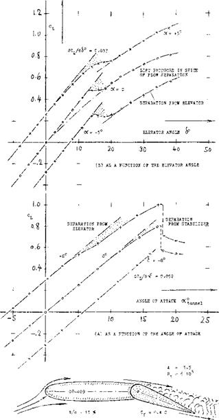
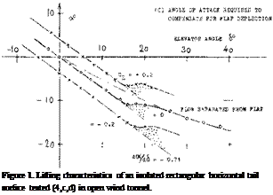
HORIZONTAL TAIL SURFACE. Experimental results of a horizontal tail surface are presented in figure 1. As a function of the angle of attack, the lift varies corresponding to a lift-curve slope dictated by the aspect ratio (1). Deflection of the elevator by plus or minus 8°, simply shifts the C^(cx) function up or down, respectively, by a c-ertain differential. Of course, at higher angles of attack, separation takes place: (a) from the suction side in general (see figure 1-а, at c<—15°) as in other foil sections; (b) from the suction side of the elevator as in figure La, at 6-8° and oC — 6°, or in figure 1-b, at 6 >- 14°. As a function of elevator deflection, as in figure 1-b, lift increases (within the range of small and moderate angles) in linear proportion to the elevator angle. For angles of attack different from zero, the lift function is shifted up and down, respectively, in a manner similar to that described above. At deflection angles exceeding 12° or 15°, flow separation takes place from the suction side of the elevator. It is evident, however, that the lift coefficient continues to increase (at a lesser rate) after passing through a more or less pronounced “dip” (3).
CONTROL EFFECTIVENESS. Through comparison of the results in parts (a) and (b) of figure 1, it s found that deflection of the elevator produces a certain lift differential per degree, equal to 71% of that due to angle of attack. In other words, the “effectiveness” of that particular elevator, Id est the lift produced by the flap in comparison to that of the surface as a whole, is
(dCL/d<$ )/(сКуЛі<х) = 0.037/0.052 = 0.71 (1)
In practical operation (when used as part of an airplane) the elevator is usually not expected to produce lift. Rather, its basic function is to cancel the lift produced by changes in the angle of attack (during maneuvers or when trimming the airplane to a different speed). It is, therefore, suitable to consider results such as in figure 1, at CL — constant. Plotting, for example for CL = zero, the elevator angle “6”, required to compensate for the angle of attack **cx‘ as in figure 1-е, a slope
dcx/d<$ = 0.71 = — (dCL./dA )/dCu/do< ) (2)
is obtained. This slope is identical to the effectiveness ratio in equation (1), except for the sign. In this text, doc/d6 is usually considered to be the effectiveness ratio, and thus used with a positive sign.
THEORY (2). Below & = 15°, figure 1 (and the later figure 17) show linear variations of the parameters plotted. It is within such limited regions of S and cX, that theory can make useful predictions as to forces and motions produced by flaps (3). The lift of a foil section is controlled by the angle of attack and by direction or location of the trailing edge (Kutta-Joukowski principle). That location can be changed by camber or by deflection of some portion of the section adjoining the trailing edge. Therefore, when deflecting the elevator as in figure 1, or the flap as in figure 3, at constant angle of attack of the forward portion of wing or tail surface, an increment of lift or normal force is produced. In the absence of skin friction, boundary layer and separation, the lift force increases in proportion to the angle of deflection “6 ” (or possibly in proportion to the sine of that angle). The deflection angle is thus the equivalent of a certain variation of the angle of attack, as indicated above by the ratio (dcx/d6 ). This ratio is a function of the chord ratio c^/c. The complete theoretical function (but not the experimental function) can be approximated by
d’cX/d<$ — V C|/c 4/1Г (4)
 CHORD RATIO. Because of the presence of the boundary layer, particular}- near the trailing edge, dcX/d6 ratios evaluated from experiments, are always less than indicated by theory. Experimental results (at small and/ or moderate angles, of deflection and/or attack) were collected from various sources; they are plotted in figure 2. Practical results are as follows:
(a) The loss of effectiveness (in comparison to the theoretical function) increases as the size of the deflected part of the chord reduces, in relation 1:0 the boundary-layer thickness.
(b) At c^/c—»-zero, the experimental function apparently joins with that corresponding to fully se parat – ed flap flow.
(c) Theory presents an upper limit to the values of do</ d<$ ; there is no simple function to express the experimental results as plotted.
(d) The simplest configuration, suitable to obtain high dc</d5 ratios, is that of plain flaps (without or with minimum gaps).
(e) Control effectiveness is reduced by section thickness and particularly by the trailing-edge “wedge” angle.
(f) When tested in presence of a fuselage, elevators do not necessarily have reduced do(/d6 ratios (5), although the lift-curve slopes, dC^/docas well as dCL/d($ , are usually reduced.
(g) Overhanging-nose balance usually increases the effectiveness ratio.
(h) Hinge or control gaps (ahead of the flap) usually reduce effectiveness.
Most of these parameters (and others) will be discussed
further under corresponding headings.
 |
 |
ASPECT RATIO. The lift-curve slope of a tail surface, such as that in figure 1, is obviously a function of its aspect ratio. Corresponding to the presence of a certain hinge gap ahead of the flap, of balancing devices and of brackets, levers and rods necessary to support and to operate the flap, that lift-curve slope is usually several % smaller than that of the plain and smooth airfoil, ft is then expected and assumed that the slope of the lift due to flap deflection dC^/dA changes with the A’- ratio in the same manner as dCL/do(. This assumption is sufficiently accurate, for practical purposes. Conditions at small Aratios where the principle no longer holds, are discussed later.
|
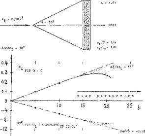
Figure 3. Lift due to, and angle of compensation of a rectangular flap attached to the trailing edge of a delta wing (6). |
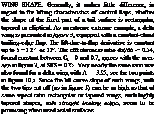
![]()
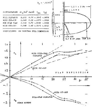 FLAP-SPAN RATIO. Control flaps do not always have a constant chord (or chord ratio) across the span, and they may not always be full-span. When averaging the flap-chord ratio, the simplest procedure is to substitute the area ratio Sp/S. It must be kept in mind, however, that lift properties (such as dc*/d6 ) art? roughly proportional to V~c^, while hinge moments roughly correspond to (cp)^. Using S^/S can thus yield misleading results, particularly in configurations where the flap span is less than the overall span of the control surface. Control flaps may be cut off or “inset” at the outer ends, or they may be cut out elsewhere (such as the elevator in figure (3/4), for example). In part-span condition, it will be best (if still approximate) to determine derivatives on the basis of a suitable average chord ratio, and to multiply the result (lift, longitudinal moment, hinge moment) with the span ratio bp/b. Analysis in (2,g) suggests that, for example, a flap on one half span only, is expected to have 0.5 lift effectiveness. A flap over half the span in the center of the “wing” may result in
0. 6 effectiveness, while a pair of outboard flaps, covering together half of the span, will only produce 0.4 times the effectiveness of a full-span flap. In other words, a cut-out in the center of a horizontal tail takes away more control effectiveness than same-size cut-offs at the lateral ends. It appears, however, that the rear lateral corners of any lifting surface have an importance for the magnitude of lift produced, which is not recognized by theory. Therefore, any deviation from rectangular flap shape, by cutting off or rounding the rear corners, is found (^,c) to reduce lift, pitching and hinge moments.


