Coupling Euler Calculations with Boundary Layer Integral Momentum Equations
As discussed before, the displacement thickness is determined such that the mass flow rate over the displaced body, at a given station, based on an equivalent inviscid flow will be equal to the mass flow rate of the viscous flow profile over the original body. Let y = yu represent the ordinate of the upper surface and in short S* = SU represent the displacement thickness along the upper surface of the airfoil.
If the Euler equations are used to represent the inviscid flow, instead of the potential flow equation, then additional considerations are necessary, since beside the continuity equation, momentum and energy equations are involved.
Le Balleur [18], has considered the general problem of matching and in the following his defect formulation will be discussed. The reader is also referred to Johnston and Soskol [19], Murman and Bussing [20] and Whitfield et al. [21] for more applications of one and two dimensional problems. Three dimensional flows over wings are considered in Ref. [22].
In the Le Balleur defect formulation, the equivalent inviscid flow problem and the viscous flow problem have an overlap region, starting from the wall and the wake center line and extends to cover the whole viscous layer. Outside the viscous layer, the viscous stresses are assumed negligible compared to the inertia terms.
For steady 2-D flows, at a given station x = constthe inviscid flow equations are
![]() df dg
df dg
dx + dy
where
|
pu |
pv |
||
|
f= |
pu2 + p |
, and g = |
puv |
|
puv |
pvz + p |
||
|
pu H |
pv H |
and
while the viscous flow equations are given by
![]() dF dG _
dF dG _
dx + dy S
where S denotes the viscous and heat transfer terms in Navier-Stokes or thin layer approximation equations.
The asymptotic matching condition is
lim (f – F) = 0 (9.53)
y^0
The defect formulation takes into consideration the variation of inviscid flow variables, including the pressure, across the boundary layer. The defect equation in vector form reads
![]() d (f – F) d (g – G) =
d (f – F) d (g – G) =
dx dy
Integration across the layer gives for example
d
pv(x, 0) = (pu — pu) dy (9.55)
dx 0
where the bar denotes the viscous flow variables.
To first order approximation, the normal momentum equation reduces to p = p across the viscous layer and the integral equations for the continuity, streamwise momentum equations are
pv(x, 0) = dL (pqs*)
![]()
![]() puv(x, 0) = pq2(в + —5*’) — pq2
puv(x, 0) = pq2(в + —5*’) — pq2
ax q 2
where q2 = u2 + v2.
co h
Spq (x, 0) = (pu — p—) dy — (pu — p—) dy
0 0
+—5*^ pq2(x, 0) = J {pu2 — pu2^ dy — J {pu2 — pu2^ dy
and h > 5.
Le Balleur considered also the effect of curvature of the wake which is not discussed here.
Following Whitfield, the energy equation, using no porosity and no slip at adiabatic surface, one obtains
![]() dh
dh
pv H (x, 0) — puH — pmH dy
dx 0
To avoid these extra calculations, an approximation consistent with boundary layers with Pr = 1 is used, where H = H = H0, hence
![]() dh
dh
pv H (x, 0) — H0 puH — puH dy
dx 0
which is the same as the equation obtained from the integration of the continuity equation.
Murman and Bussing [20] applied Le Balleur’s defect formulation for compressible flow in a convergent-divergent nozzle and used boundary layer approximations for the viscous flows. The matching conditions used are
u = и, H = H, p = p, and v = v, at h > 5 (9.62)
The first three conditions are used in the boundary layer calculations. Therefore, one additional condition must be specified to enforce the matching. The boundary conditions for Euler equations will be derived using the fourth condition in three cases: the equivalent inviscid flow at the boundary layer thickness y = yu + 5; or at the original body y = yu; or at the displaced body y = yu + 5*.
Integrating the continuity equation from the body surface to S yields
![]() d rS dS
d rS dS
 |
|
pudy – (pu)s — + (pv)s = 0 dx 0 dx
and since (pu)S = (pu)S, the above equation reduces to
dS d
(pv)s = (pu)s dx – dx ((pu)s (S – S )) (9.66)
This is the entrainment equation, where the second term represents the entrained mass flow rate. The second term is usually negative and it is the only boundary condition at y = S required for the Euler equations calculations (subsonic boundary condition).
Instead, if the continuity equation is integrated from S* to S and enforcing the matching conditions, one obtains
dS* d S ( pu,
(pv)l’ =(puk – dx + dx (pu)SJs, (‘ – TdXdJ dy (9’67)
If the gradient of the equivalent inviscid flow is negligible in the region S* < y < S, then the last term drops and the flow is tangent to the S* surface. In this case, the no penetration surface boundary condition is imposed for the Euler calculations.
If the inner boundary condition of the inviscid flow is located at the original surface, the standard definition of S* is used, and the transpiration boundary condition reads
(pv)0 = dx {(pu)§S*) (9.68)
In most regions, the body will be an inflow boundary, which means that three characteristics are pointing into the domain and one points out. The above matching condition provides only one. The inviscid flow is not uniquely determined! (For potential flow, the total pressure and total enthalpy are constant and the transpiration boundary condition uniquely determines the flow).
To determine the inviscid flow governed by the Euler equations, Johnson and Sockol integrated the momentum and energy equations from the body surface to S to get
(puv)0 = usd – ((fju)s S*) + d – py2 + p^ – ^pu2 + p) J dy
![]()
![]() д P.
д P.
/
d d S
(pvH)0 = Hs (pu)s S*) + (puH) – (puH)s) dy
dx dx 0
( dH
+ S pu— (9.70)
Only for weak interaction and isoenergetic external flows, the second and third terms in the above equations can be ignored. In this case, one can use u0 = uS and H0 = HS, i. e. assigning the edge values of u and H to the transpired mass (this strategy is however valid for strong interaction regions as discussed by Le Balleur [18]).
Whitfield and Thomas [21] used a reflection boundary condition for their Euler calculations, namely
du д H
= 0, and = 0 (9.71)
dy dy
at the body surface.
Again, these conditions are valid only for weak interactions.
Murman and Bussing [20], simulated compressible flow through a nozzle using the following quasi-one dimensional equations
![]() d (puA) (puS*)
d (puA) (puS*)
dx dx
d {(p,‘2 + P)A) = 2 A U(S* + o,) – C.
dx dx
d (puHA) = 2d_ (PuH(S* + Oh)) + St
(dx* (dx*
where
![]()
and St is the Stanton number.
The right hand sides represent sources of mass, momentum and energy for the equivalent inviscid core flow. Murman and Bussing calculated the inviscid flow based on the above equations and compared the results using inviscid flow with equivalent area, A* = A – 2nRS*, and both calculations are in good agreement, confirming the conclusions regarding the weak interaction case. The strong interaction case is still a problem and other approaches will be considered later following Cousteix and Mauss [23]. (Le Balleur used his defect formulation only for potential flows; Euler equations were not considered).
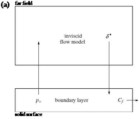
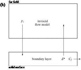
Le Balleur [18] studied the stability of the coupling procedures using harmonic analysis for both subsonic and supersonic flows, with attached and separated boundary layers and introduced a new semi-inverse iterative method for steady and unsteady transonic airfoils with shocks. To put his work in perspective, comparisons among the available methods and their limitations are useful. The standard direct method, discussed before, does not converge for separated flows in general. Following Catherall and Mangler [24], the inverse methods have been used by many researchers. However, such methods may not converge for attached flows. Figure 9.6 depicts the inverse and direct coupling procedures.
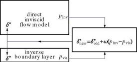
In a fully inverse method, the boundary layer equations are solved with a given displacement thickness and the outer edge velocity is calculated and fed to the inviscid flow calculations. To avoid the difficulties of both methods, Carter [25] introduced a semi-inverse method. In this method, starting with a displacement thickness both a direct inviscid flow calculation and an inverse viscous flow calculation are performed separately, then a correction formula, based on the difference on the inviscid surface pressure and the viscous pressure at the edge of the boundary layer, is used to update S*, seeFig.9.7.
At convergence, pi and pv are the same.
Le Balleur pointed out the limitations of Carter’s method and proposed an important modification based on his harmonic analysis, namely the correction formula is changed to

![]()
![]() S*ew = S0id + fi Stew = S*oU + f2
S*ew = S0id + fi Stew = S*oU + f2
Underrelaxation of S* is used to guarantee convergence for all cases. Before we discuss the Fourier analysis and stability of the coupling methods, two other methods are outlined. Brune et al. [26] introduced the fully simultaneous method which is shown in Fig. 9.8.
The potential flow calculations should provide the relation
![]() up = up (S p)
up = up (S p)
|
|
 |
|
 |
|
|
|
|
|
![]()
|
|
|
|
|

Fig. 9.8 Brune et al. [26] coupling procedure while the boundary layer calculation gives
SB = SB (u в) (9.79)
The matching conditions are
Sp = SB and uP = uB (9.80)
In general, the potential equations are non linear. Upon linearization around an initial guess, the change of uP, AuP, can be obtained in terms of change of Sp, ASp, through an influence matrix, A P
Au P = AP ASP (9.81)
Similarly, the perturbed boundary layer equations gives
Au B = AB AS’B (9.82)
A first approximation to the matching conditions is
SP + ASP = SB + ASB (9.83)
The above four relations are solved simultaneously to obtain the corrections to uP and SB and the process is continued until convergence.
To simplify the above procedure, Veldman [27] introduced the Quasi-simultaneous method as in the following Fig. 9.9.
Veldman demonstrated the advantage of his procedure in a series of papers. Cebeci [28] also used similar procedures. Careful treatment is necessary for the case of transonic flows, since the linearized inviscid flow equations are of mixed type. Ignoring this feature, as in some published works, may lead into problems. A comprehensive review is published in Ref. [30].
The following quasi-simultaneous coupling method has been successfully used by Wigton and Holt [29] for transonic flows Fig. 9.10.


