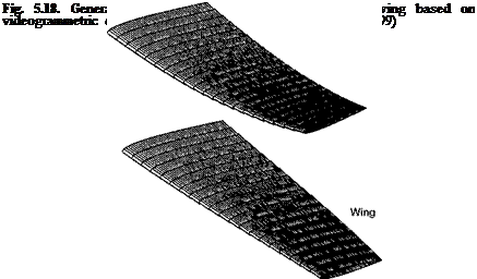
Generation of Deformed Surface Grid
For a more accurate representation of data, PSP and TSP results in images should be mapped onto a deformed surface grid of a model rather than a rigid surface grid when the model undergoes a large deformation in wind tunnel tests. Aeroelastic deformation data for a model can be obtained using videogrammetric model deformation (VMD) measurement technique (Burner and Liu 2001). Hence, PSP and TSP systems should be integrated with a VMD system for fusion of pressure and temperature data with deformation data (Bell and Burner 1998; Liu et al. 1999). There are two approaches for integration of PSP/TSP with VMD. The first approach uses PSP/TSP simultaneously with VMD as a separate and independent system, while VMD, that is operated under the PSP/TSP lighting and surface conditions, provides deformation data for generating a deformed surface grid. The advantage of this approach is that the structure of a PSP/TSP system is not changed and PSP/TSP operation suffers no interference from VMD operation in large production wind tunnels. In contrast, the second approach uses the same camera for both PSP/TSP and VMD measurements at the same time; VMD software is integrated as an additional part of the PSP/TSP software package. Instead of a nearly normal view of a camera for pure PSP/TSP application, the combined system requires an oblique viewing angle of a camera to achieve good position sensitivity for VMD measurements.
Usually, VMD gives wing deformation characterized by the twist and bending of a wing. When the local translation and twist are measured by VMD at different spanwise locations of a wing, a transformation of translation and rotation can be used to generate a deformed surface grid of the wing. At a spanwise location Y,
5.7. Generation of Deformed Surface Grid 113
the deformed coordinate (X’ ,Y, Z ) on a wing surface grid is locally related to the non-deformed grid coordinate (X, Y,Z) by
 |
 |
||
The translation vector at a spanwise location Y of the wing is (Tx, Tz) and the rotational matrix is

where the twist 9twist is a function of the spanwise location Y. When the bending relative to the wingspan is small, the spanwise location does not change much, i. e., Y’ ~ Y, and the wing airfoil section remains the same. For illustration, we consider a fictional wing with a NACA0012 airfoil section and assume that the spanwise distributions of twist and bending are given by dtwist =- 5(Y/b)3, Tz = 0.08b(Y/b)3 and Tx = 0, where b is the semi-span of the wing. Figure 5.18 shows a deformed surface grid generated using a transformation of translation and rotation.


