Hovering Micro Air Vehicles
A micro air vehicle (MAY) has been defined variously as an aircraft having a maximum dimension of 15 cm (~ 6 in) to as much as 40 cm (~ 16 in). MAVs are being designed to meet the requirements of various military missions at affordable cost. While having the obvious advantage of small scale and correspondingly low radar cross section, MAVs can potentially provide for reconnaissance capability advantages with rapid deployment and real-time data acquisition capability, with stealth and relatively low noise. Being able to operate autonomously is obviously an added capability of much military value. These capabilities can offer the modern military increased situational awareness and greater combat effectiveness with fewer casualties.
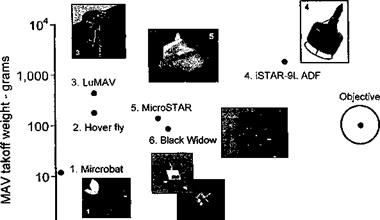
There are two VTOL types of MAV configurations that received interest, those based on rotating-wings and those with flapping (reciprocating) wings. As shown in Fig. 6.42, all existing MAV designs fall well short of the desired empty weight, payload and endurance objectives because they have not yet shown credible aerodynamic efficiency [see Bohorquez et al. (2003) and Tarascio & Chopra (2003)] or sufficiently good specific fuel consumption. Rotating-wing MAVs operate at blade chord Reynolds numbers that may be three orders of magnitude lower than full-scale helicopters. This produces thick boundary layers on the blades and results in large values of profile drag (see Fig. 7.4 as well as Sections 6.4.7 and 7.13). The resulting poor lift-to-drag ratios of the blade sections decrease substantially the net rotor efficiency (the figure of merit). In concert with this effect is the typically high induced power requirements associated with MAV-scale rotors. Specific problems of engine efficiency at this scale must be also considered, including increased friction and thermal losses and significantly decreased overall engine efficiency. In addition, for internal combustion engines there are carbureation and fuel-air mixing issues associated with low intake Reynolds numbers.
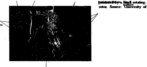
The underlying reason for high induced aerodynamic losses from a rotating-wing MAV can be seen in the structure of the rotor wake, an example of which is shown in Fig. 6.43.
|
14———- 1———- 1———– 1————- 1 і і 0 10 20 30 40 50 60 Flight endurance – mins. Figure 6.42 The domain of weight-endurance for some hovering MAV designs. Adapted from Tarascio & Chopra (2003). |
The wake was visualized using smoke and laser sheet illumination (see Section 10.2.2). While the helicoidal wake structure is qualitatively similar to that found on rotors at much larger scale (see Figs. 2.2, 2.4, and 10.5), with clear evidence of the tip vortices on the periphery of the wake boundary, the most noticeable difference at this small scale is the very thick, turbulent vortex sheets in the rotor wake. These sheets are formed by the merging of the thick boundary layers on the upper and lower surfaces of the blade sections, which operate at Reynolds numbers of less than 104. These sheets are then convected downward in the wake below the rotor, undergoing a stretching and folding process. The net result is a relatively wide, conical, turbulent inner wake region that occupies a substantial fraction of the slipstream area. This means that an increased mass flow is necessary to produce the same change in vertical momentum of the fluid through the control volume surrounding the rotor and its wake. The net result for the MAV is larger induced losses to generate a given thrust, a higher effective disk loading, and much reduced hovering efficiency.
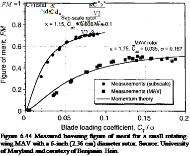
The measured hovering performance of this MAV is shown in Fig. 6.44 in terms of figure of merit (FM) as a function of blade loading coefficient. Notice the relatively low value of maximum FM obtained by the MAV (about 0.5) compared to a larger rotor (about 0.75), even at subscale. This loss of performance can be modeled within the context of the momentum theory with a nonideal wake contraction, as discussed for the ducted fan in Section 6.10.1. The ideal induced power coefficient for the MAV can be written as
![]()
 |
(6.56)
where aw is the wake contraction parameter. Note that aw = 0.5 for an ideal rotor with a 2:1 wake area contraction and aw = 1 for an ideal ducted fan with no wake contraction. In the case of the MAV, aw < 0.5 and is probably close to 0.25 based on the flow visualization shown in Fig. 6.43. Using Eq. 6.56 allows the figure of merit for the MAV to written
 |
|
in the conventional way as
In this case the value of к is about 1.75 based on the asymptotic value of the measured FM curve, and ^ 0.035 based on low Reynolds number airfoil data (Fig. 7.4). Figure 6.44 shows that the momentum theory compares well with the measurements, but only if the wake contraction parameter, aw, is set to about 0.25. This confirms that because of the thick viscous wake losses the MAV rotor behaves as if it were being operated at a much higher disk loading, and combined with a high induced power factor and large profile drag, this gives the MAV relatively poor efficiency compared to a rotor operated at larger scale. This makes the value of rotating-wing MAVs less attractive because they require higher power with the result of reduced payload, range, and endurance. It is likely that future advances in understanding extremely low Reynolds number aerodynamics will lead to the improved viability of the rotating wing MAV concept. Already novel ideas such as blade surface heating-cooling or the application of Gurney naps are showing some promising results but with dubious gains in net vehicle performance – see Kim et al. (2003) and Nelson & Koratkar (2004). One key to improved performance obviously lies within the viscous dominated wake structure and the need to reduce induced losses not just profile losses.
As a consequence of these poor efficiencies, the flapping wing MAV concept has received some attention [see Woods et al. (2001)], and this seems to offer the potential of developing MAVs with improved hovering performance capability at these very low flight Reynolds numbers. The reasons are apparent from studies of autorotating seeds [Azuma & Yasuda
 |
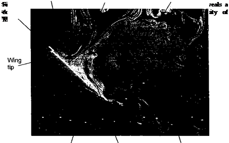
(1989)] and also measurements on flapping wings themselves – see review by Sane (2003). While showing only average lift-to-drag ratios in the range of 2 to 4, the ability to generate maximum lift coefficients of 2 or more is of considerable significance for low Reynolds number flight. However, it would be naive to conclude that somehow flapping wings were more aerodynamically efficient than a rotor and, therefore, are more well-suited for low Reynolds number flight. The physics of flapping wing aerodynamics is extremely complicated because it involves unsteady aerodynamic effects, large regions of flow separation and the production of highly vortical flows; see Sane (2003), Lehmann (2004), Singh et al. (2005), and Ramasamy et al. (2005). An example of flow visualization that was conducted on a small flapping wing vehicle is shown in Fig. 6.45, which clearly reveals leading-edge and mid-chord vortical structures that augments wing lift. These are not stable structures and are cast off the wing continuously for much of the flapping cycle. A stronger “starting vortex” is cast off as the wing rotates about its pitch axis (supination) and as it changes its direction for the second half of the flapping cycle. The process is repeated when the wing direction reverses again at the other end of the stroke (pronation). This vortical shedding process in many ways resembles the problem of dynamic stall, which is discussed in Chapter 9, although the low aspect ratios of typical flapping wings makes the problem considerably more 3-D than found even on helicopter rotor blades. The flapping process also continuously trails a pair of tip and root vortices into the wake that are laid down as a set of folded, interacting wake structures, a structure it seems that is difficult to generalize. Zbikowski (2002) suggests that some prediction capability of the unsteady aerodynamic forces on flapping wings might be achieved using unsteady thin airfoil theory (such as the methods given in Chapter 8), but the extremely nonlinear nature of the problem clearly offers considerable opportunities for new research.


