Incompressible Flow About Thin Wings
Thin wing theory is an efficient tool for the study of the spanwise variation of aerodynamic characteristics which has effect on the total lift and moment coefficient of a finite wing. This variation is considerably slow except at the tip region of the high aspect ratio wings. For low aspect ratio or delta wings, on the other hand, the aerodynamic characteristics vary rapidly in their short span. Another characteristic of the finite wing theory is the downwash generation because of the tip vortices, which in turn induces drag. The magnitude of the induced drag is proportional with lift and inversely proportional with the aspect ratio. The physical model we use for the three dimensional aerodynamic analysis is based on the two dimensional vortex sheet spread over the wing surface and its wake. In this model, imposing the boundary conditions on the wing the spanwise and the chordwise components of the vortex sheet strength are expressed in terms of the downwash as an integral equation. The remaining task now is the inversion of this integral equation with different assumptions relevant to the flow conditions. Let us now build our model for different wing shapes to find the aerodynamic coefficients.
4.1 Physical Model
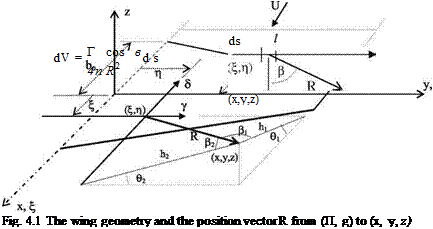
Let the unsteady components of the vortex sheet strength on the wing surface immersed in a free stream with angle of attack be given by y(x, y, t) in spanwise direction and be given by d(x, y, t) in chordwise direction, respectively. In Fig. 4.1, shown are the wing surface in the free stream and the relevant geometry for the point (x, y, z) at which the vortex sheet induces the downwash under consideration.
According to the Biot-Savart law the infinitesimal vortex with intensity of Tds located at a point (П, g) induces a differential velocity dV at a point (x, y, z) as
follows
U. Gulfat, Fundamentals of Modern Unsteady Aerodynamics, 95
DOI: 10.1007/978-3-642-14761-6_4, © Springer-Verlag Berlin Heidelberg 2010
 |
The relations between the distances and the angles become
R = (x – П)2+(у – g)2+z2, Й1 = R cos b1, h2 = R cos b2-
 |
 |
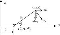
Viewing the x-z plane from у-axis, we can find the differential velocity dVj induced by the spanwise vortex sheet component у as follows
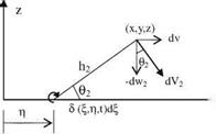
Similarly, looking at y-z plane from x axis, dV2 component induced by y d can be written as
1 S(у – q)d%dq 2 _-4n R
![]()

1 Szd^dq
‘4П R
The induced velocities given above are in differential form of the perturbation velocities. If we want to find the effect of whole x-y plane we have to find the integral effect to obtain the total induced velocity components at a point (x, y, z) as follows
![]() ,, + 1 Z c(n f)zdndg
,, + 1 Z c(n f)zdndg
(-Гy, z, 0 = — – – – -3=2,
4p (x – П)2 + (y – g)2 + z2
The components of the induced velocities at the lower and upper surfaces of the thin wing have the following relations for z = 0±
u'(x, y, 0+, t) = – u'(x, y, 0-, t) and v(x, y, 0+, t) = – v(x, y, 0-, t).
Now, we can write the relation between vortex sheet strength components and the perturbation speeds.
c(x, y, t) = u'(x, y, 0+, t)-u'(x, y, 0 , t)=°x – 0/1 and,
d(x У, t) = v(x У, 0+, t)-v(x, У, 0- t) = 0/u – ^y1.
In the last two lines, if we take the derivative of the first equation with respect to y, and the second equation with respect to x, they become equal, i. e.,
Due to the presence of the wing in a free stream, there are three distinct flow regions: (i) the wing surface Ra, (ii) wake region Rw, and (iii) rest of the area in x-y plane.
In addition, we can define the lifting pressure as the pressure difference between the lower and upper surfaces of the wing as follows,
Dp = pi – pu
The Kelvin’s equation can be written for the pressure differences of the wing surface and the wake region
X
“p = o~tj t)dn + UУ; t) (43a)
Xi
Xt X
= Ojt Уа(П; V; t)dn + Ojt У Cwfe V; t)dn + U7w(X; У; t) (4-3b)
X
At this stage, we can consider the downwash as the velocity induced separately by the vortex sheet of the surface and the wake region
If the equation of the wing surface is given as z = za(x, y, t), the downwash on the surface becomes,
In the wake region, since there is no lifting pressure the unsteady Kutta condition becomes
—Pw(x, y, t) = 0; (x, y) c Rw (4.6)
In the rest of the x-y plane, there is no vortex sheet in our model.
The remaining task here is to find the lifting pressure in terms of the surface vortex sheet strength given as 4.3a. The surface vortex sheet and the wake vortex sheet strengths are related to each other via unsteady Kutta condition, 4.3b and 4.6, This relation is used to eliminate the wake vortex from Eq. 4.4. If we now use 4.5 to express the downwash in terms of the equation of surface, we obtain the integral relation giving the surface vortex sheet strength in terms of motion of the wing. The resulting integral equation contains double integral, and quite naturally it is not analytically invertible! Depending on the geometry of a planform we can make simplifying assumptions to this integral equation and find approximate solutions. It is convenient to start inverting the equation for steady flow.


