PITCHING MOMENTS DUE TO FLAPS
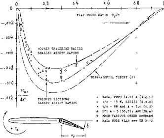
Flap/Chord Ratio. Deflection of a trailing-edge flap produces an additional longitudinal moment identical in character to the zero-lift coefficient Cmo of foil sections. In other words, this moment is independent of lift and reference axis. Figure 4 shows the slope of the coefficient, plotted against the chord ratio. The theoretical moment displays a maximum at c^/c ^ 0.26. The experimental values are all smaller than predicted, because of presence and growth of the boundary-layer. Pressure losses encountered near the trailing edge have to be made up by increased lift forces near the leading edge. In the vicinity of c^/c =■ 0.3, tested moments are thus between 75 and 80% of the theoretical values.
|
Figure 4. Pitching moment due to trailing-edge flap deflection as a function of chord ratio. |
COMPARISON WITH CAMBER. Deflection of a flap represents a variation of section shape similar to camber. Considering position and direction of the trailing edge, 1 degree deflection of a flap hinged at 0.5 of the foil – section chord, represents geometrically 0.25/57.3 =
0. 43°^ camber. The corresponding value of Cmo (as found for */c — 0.5, in the “foil section” chapter) is 0.025 (0.43) « 0.010, while figure 4 indicates a slope of 0.007. The difference is due to the different type of curvature of the camber line; the tangent angle of that line at the trailing edge, is usually larger in a cambered foil section.
 |
THICKNESS RATIO. Both pressure distribution and boundary-layer growth are a function of foil-section thickness ratio. Consequently, the pitching moment due to flap deflection varies with that thickness ratio. The value of the derivative dCm/d6 , as plotted in figure 5, decreases as the thickness ratio is increased, thus explaining some or most of the spread in figure 4. A parameter better suited than thickness ratio, to correlate pitching moment derivatives, would probably be the trailing-edge “wedge” angle (as in the later figure 13).
MOMENT DUE TO LIFT. As in plain airfoil sections, the aerodynamic center of a flapped section might be expected not to be exactly at the quarter-chord point. Statistical evaluation in (4,d) shows that the A’ center of “conventional” flapped sections is approximately at x/c = 220/o, which is 1 or 2^° ahead of the usual location in such sections. The total of the pitching moment of a symmetrical, but flapped foil section, taken about the leading edge (with a “dot” to indicate this definition) thus corresponds to
Cm. « (dCmo/d6 — (x/c)CL (6)
where (dCm0/dA) as in figures 4 and 5, and where x/c = location of the aerodynamic center. [77] [78] [79]
The lift of a symmetrical but flapped foil section can be considered in two components. The first, corresponding to angle of attack, is at or near (or ahead) of 0.25 of the chord. The second component is the differential added through flap deflection, at constant angle of attack. Its location in two-dimensional flow
xA/с = (ACMt/ACL) (10)
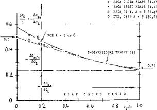
– is theoretically expected to be at 0.5 of the chord for flap-chord ratios cp/c approaching zero. Figure 6 shows how the “A” location reduces from there as the chord ratio is increased. In three-dimensional flow (corresponding to finite aspect ratios) the “Д” location is further aft, however. Thus considering a tail surface, for example at c< – zero, the lift produced by flap deflection corresponds to
Дси = (dCL/dA ) & =: (dCL/d<x) b (dcX/dA) (12)
The moment due to this lift coefficient corresponds to
ACm. = (dCm/dcS) 6 – f (dCm,/dCL) (АСц) (13)
The center of pressure of AC^is then found to be at
хд/с = – (dCmo/d<5 )/(dCL/d<*) – (dCm./dCL ) (14)
It is obvious that (dCL/dcx) and (dCL/d<i ) are functions of the aspect ratio. Using average tested values for all the derivatives involved, we have computed “A” locations for two different “lift angles” and aspect ratios. They are plotted in figure 6 together with some experimental results. It then becomes evident that the “Д” location for cp/c between 0.1 and 0.2 and for A between 4 and 10, is in the vicinity of 50%of the chord; and this location is as that in equation (10).
|
Figure 6. Center of pressure location of the lift produced by flap deflection. |


