RIGID BODY EOM
When describing aircraft flight path, it is necessary to mention the reference axis system of the aircraft and its relation to the Earth. Thus, a proper understanding of the various axes systems and their transformation is of importance. The frequently used axes systems are the inertial, Earth, body, wind, and stability axes and their definitions are as follows.
 |
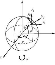
Inertial axis: The origin of inertial axis system is assumed to be the center of the Earth. This reference frame is assumed to be stationary with the z-axis pointing to
|
z
FIGURE 3.3 Inertial axis system. (From Chetty, S. and Madhuranath, P. (ed.), Aircraft Flight Control and Simulation, NAL Special Publication 9717, FMCD, NAL, 1998.) |
the North Pole and the x-axis pointing to 0° longitude (Figure 3.3). The y-axis, perpendicular to the XZ plane, completes the right-handed orthogonal axis system.
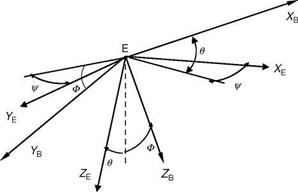
Earth axis: The origin of the Earth axis system lies on the surface of the Earth, with the X – and Y-axes pointing to the north and east directions (NED). The z-axis points down toward the center of the Earth. This reference frame is fixed to the Earth and, at times, is referred to as the NED frame (Figure 3.4). For most aircraft modeling and simulation problems, it is assumed to be the inertial frame of reference where Newton’s laws are valid.
Body axis: The origin of the body axis system is fixed to the aircraft’s CG, and therefore rotates and moves in space along with the aircraft. The X-axis points forward through the aircraft’s nose and is called the longitudinal axis, while the positive
|
|
|
FIGURE 3.5 Body axis system. |
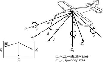
direction of the Y-axis is along the right wing and is known as the lateral axis. Thus, the X – and Y-axes are aligned with some geometric features of the aircraft. The Z-axis is perpendicular to the XY plane and points toward the Earth when the aircraft is in straight and level flight (Figure 3.5). In an alternative principal body axis, the X-axis is aligned with the principal inertia axis. Thus, the cross product of inertia, Izx, is zero. This would simplify the lateral EOM. Interestingly, the aerodynamic body axis (also known as stability axis in the United States and wind axis in the United Kingdom) has the X-axis aligned with the projection of the velocity vector, in a datum flight condition, onto the plane of symmetry. The aerodynamic body axis is at an angle a relative to the geometric body axis. Since, these axes are ‘‘natural’’ axes systems, they are used to define the basic aerodynamic forces, lift, and drag. The body axis angular rates and Euler angles are naturally measured quantities. This system is consistent in the use of the force coefficients in the body axis. However, it yields nonlinear observation equations for flow angles and velocity and also has singularity at a pitch angle of 90°. Interestingly, the pilot is aware of the rotations of the aircraft about its CG, rather than any other axis fixed in space. The pilot ‘‘feels’’ the accelerating movement of the aircraft because his alignment is in the body axis system.
Wind axis: The origin is at the aircraft’s CG with the X-axis pointing forward and aligned to the velocity vector. The positive Y-axis passes through the right wing and the Z-axis points downward. The aircraft flow angles (angle of attack and sideslip) define the relation between the wind and the body axis system (Figure 3.5). Since the direction of the aircraft velocity vector keeps changing during the flight, the wind axis system, unlike the body axis system, is not fixed.
Stability axis: This axis system is similar to that of body axis. The origin is at the aircraft’s CG and the Y stability axis is aligned with the Y body axis that passes through the right wing. The X stability axis is inclined to the X body axis at an angle AOA (Figure 3.6).
The aerodynamic data are generated in a wind tunnel in body axis or in stability axis. Thus, a clear understanding of the various axes systems used and the ability to transform from one to the other is essential to the study of aircraft dynamics. The axes systems are lined together by the direction cosine matrix, which is a function of the Euler angles f, U, C (Appendix A has more details on axis transformation).
|
|
|
Earth fixed
frame
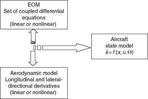
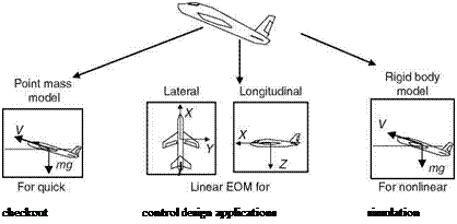
As mentioned earlier, the core issue in flight mechanics is to evaluate the aircraft performance and dynamics. To evaluate aircraft performance indices such as range, rate of climb, takeoff, and landing distance, the aircraft is generally treated as a point mass model and its lift, drag, and thrust forces are identified. Although the point mass model is useful for a brief description of aircraft dynamics, the complete six-degree-of-freedom (6DOF) nonlinear equations would be required for a detailed description of aircraft dynamics. In between these two extremes lie the linearized models, which are useful for control design applications (Figure 3.7).
 |
Expecting the aircraft to behave like a dynamic system in flight, an input given by the pilot will cause the forces and moments acting on the aircraft to interact with its inherent natural characteristics, thereby generating responses. These responses
contain the natural dynamic behavior of the aircraft, which can be described by a set of equations called EOM with certain important assumptions.
1. Aircraft is a rigid body. This assumption, though strictly not valid, is sufficiently accurate for describing aircraft motion in flight. It allows the aircraft motion to be described by the translation of and the rotation about its CG. In reality, various components of an aircraft might move in relation to each other: engine, rotorcraft disk, control devices, and bending of wings (this brings aspects of aeroelasticity into flight dynamics problems) due to air loads.
2. Earth axis system can be used as the inertial frame of reference in which Newton’s laws are valid, and the Earth is assumed to be fixed in space.
3. Aircraft mass is constant. Though not always true, the mass distribution of the aircraft is assumed to be invariant.
4. Earth is flat for the period of time of dynamic analysis. The curvature effects would have to be taken into account only for long-range flights (e. g., missiles, spacecrafts, etc.).
5. XZ plane in aircraft is a plane of symmetry.
6. Steady flight is assumed to be undisturbed. This will simplify several equations, according to the needs of the case. If flow angles are assumed to be small, then sine and cosine terms would be simplified. This would render the applicability of the EOMs to the conditions where small perturbations could occur.
These basic assumptions are appropriately used in formulating the EOMs and their simplification as the case might be.
The EOM of the aircraft can be written by considering its linear and angular momentums.
Let p be the linear momentum vector (mV) and H the angular momentum vector, each measured in the inertial reference frame. Newton’s second law states that the summation of all the external forces acting on a body is equal to the time rate of change of momentum of the body:
![]() dp = d(mv) = v F dt ~ dt ~ ^
dp = d(mv) = v F dt ~ dt ~ ^
Similarly, the summation of all external moments acting on the body is equal to the time rate of change of the angular momentum (moment of momentum):
Referring to the inertia and angular velocities in the space fixed inertial frame, the inertia tensor will change as the aircraft rotates about the axes. This would contribute to dH/dt through dl/dt and the resulting equations would have time variant parameters. To overcome this, we consider the body axis system that is fixed to the aircraft so that the rotary inertial properties are constant. This implies that the vector quantities V and H in Equations 3.1 and 3.2 need to be determined in the body axis.
A vector in a body axis frame, rotating at an angular speed of ш, can be represented by the following equation:
Here, subscripts І and B refer to the inertial and body axes frame of references. Using the above expression, the forces and moments in the inertial axis system can now be represented in the body axis system as follows:
It must be emphasized here that the mass is assumed to be constant. This would not be the case for long-range aircraft flights, missiles, and spacecrafts because of expending of fuels/shedding away certain extended components/stages, etc.
The inertial forces and moments can now be resolved in the body axis system.


