SMAL – DISTURBANCE FLOW OVER TWO-DIMENSIONAL AIRFOILS
The strategy presented in Chapter 3 postulates that a solution to the potential flow problem can be obtained by superimposing elementary solutions of Laplace’s equation. Thus, the solution consists of finding the “right” combination of these elementary solutions that will fulfill the zero normal flow boundary condition. Using this approach, in the previous chapter the small-disturbance problem for a wing moving with a steady motion was established. This treatment allowed us to separate the problem into the solution of two linear subproblems namely the thickness and lifting problems. In this chapter the simpler two-dimensional case of both the airfoil with nonzero thickness at zero angle of attack and the lifting zero-thickness airfoil will be solved, by using analytical techniques. These solutions can then be added to yield the complete small-disturbance solution for the flow past a thin airfoil.
4.2 SYMMETRIC AIRFOIL WITH NONZERO THICKNESS AT ZERO ANGLE OF ATTACK
Consider the two-dimensional symmetric airfoil, with a thickness distribution °f Vt(x), at zero angle of attack, as shown in Fig. 5.1. The velocity field will be
x FIGURE 5.1
![]()
![]()
![]()
![]()
 Two-dimensional thin symmetric airfoil at zero angle of attack.
obtained by solving the continuity equation:
![]() У2Ф = 0
У2Ф = 0
with the boundary condition requiring that the flow normal to the airfoil upper (+t?() and lower surface (-»),) be zero:
 (5.2)
(5.2)
This equation actually states that the sum of the free-stream and the airfoil-induced normal velocity components is zero on the surface
Equation (5.2) is the two-dimensional version of the three-dimensional boundary condition (Eq. (4.30)) and Ф is the perturbation velocity potential. Recall that the boundary condition has been transferred to the z — 0 plane. Also, the boundary condition requiring that the disturbance due to the airfoil will decay far from it (Eq. (4.2)) is not stated because it is automatically fulfilled by the source element.
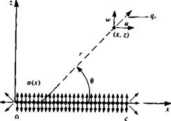
Because of the symmetry of the problem (relative to the z = 0 plane) the use of a source distribution is selected that inherently has such a symmetric feature. These sources are placed on the x axis from x = 0 to x = c, as shown in Fig. 5.2. The potential of a source distribution can be obtained by observing the potential due to a single source element of strength a0, located at (jc0. 0)
The local radial velocity component qr due to this element at an arbitrary point (x, z) is (the tangential component is zero):
In cartesian coordinates this can be resolved into the x and z directions as (и, w) = <7r(sin в, cos в). The same result can be obtained by differentiating Eq. (5.3):
 (5.5)
(5.5)
![]() ЭФ oo °p *
ЭФ oo °p *
yy ———– ————————-
dz 2л (x – x0)2 + z2
As shown in Fig. 5.2, the airfoil thickness effect is modeled by a continuous o(x) distribution along the x axis. The velocity potential and the resulting velocity field can be obtained by integrating the contribution of the above point elements over the chord (from Jt = 0, to r = c); however, now o(x0) is the source strength per unit length.
|
-i; |
f o(x0) In V(* – *o)2 + Z2 dx0 Jo |
(5.7) |
|
ЧЯ II 3 |
(5.8) |
|
|
, ч 1 |
fc z |
(5-9) |
|
w(x, 0±) = lim w(x, z) = ± z—*±0 |
In order to substitute the velocity component w(x, 0) into the boundary condition (Eq. (5.2)) the limit of Eq. (5.9) at z = 0 is needed. Following the results of Section 3.14,
![]()
 FIGURE 5.2
Source distribution model for the thin symmetric airfoil.
 |
where + is on the upper and – is on the lower surface of the airfoil, respectively. Similarly to the three-dimensional case, this result can be obtained by observing the volume flow rate due to а Ас long element with a strength a(x), as shown in Fig. 5.3. As dz—*0, the flux from the sides of the small element becomes negligible, compared to the flux due to the w(x, 0±) component. The volumetric flow due to a Ajc wide source element is o(x) Ax, which must be equal to the flow rate fed by the two sides (upper and lower) of the surface 2w(x, 0+) Ajc. Therefore,
Substituting Eq. (5.10) into the boundary condition results in
or
 (5.11)
So in this case the solution for the source distribution is easily obtained after substituting Eq. (5.11) into Eqs. (5.7-5.9):

![]()
![]() (5.12)
(5.12)
(5.13)
(5.14)
It is clear from these equations that the и component of the velocity is
symmetric, and the w component is antisymmetric (with respect to the x axis). Therefore the pressure distribution is the same for the top and bottom surfaces and is evaluated at z = 0. The axial velocity component at z = 0 is then
and the pressure is obtained by substituting this into the steady-state Bernoulli equation (Eq. (4.52)):
ЭФ
p-p^=~pQo. — =~pQ^u{x, 0) (5.16)
|
„ “(*> 0) |
and in terms of the pressure coefficient
By evaluating the velocity at z = 0±, as in Eq. (5.15), the pressure coefficient becomes

![]()
![]() -2 fc drj,(x0) 1
-2 fc drj,(x0) 1
dx (x – x0)
Since this pressure distribution is the same for the upper and for the lower surface the pressure difference between the upper and lower surface is zero:
Лр=Р/-ри = 0 (5.19)
and the aerodynamic lift per unit width is
L= Apdx = 0 (5.20)
Jo
For the drag force per unit width calculation the contributions of the upper and lower surfaces need to be included using Eq. (4.55):
<5’21)
 |
|
Substituting the pressure from Eqs. (5.15) and (5.16) into Eq. (5.21) and observing that the integral of a constant pressure p„ over a closed body is zero yields
It can be shown, using the symmetry properties of the integrand (see Moran,51 pp. 87-88) that the drag is zero:
This result can be obtained directly from the Kutta-Joukowski theorem (Section 3.11). Thus, the symmetrical airfoil at zero angle of attack does not generate lift, drag, or pitching moment. Evaluation of the velocity distribution needs to be done only to add this thickness effect to the lifting thin airfoil problem (as derived in the next section).
To obtain the velocity components from Eqs. (5.13) and (5.14) for points not lying on the strip (0<дг<с, z = 0), the integrals can be evaluated numerically or in closed form for certain simple geometries. However, when the axial component of the velocity or the pressure coefficient is to be determined on the airfoil surface using Eqs. (5.15) and (5.18) it is seen that the integrands become infinite at x=x0 and the integrals are not defined. It is noted that if the thickness is increasing at де = x„, the integrand goes to -« as jc„ is approached from the left and to +» as x0 is approached from the right (e. g., in Eq. (5.15)) and the integrand is antisymmetric in the neighborhood of x = X,).
If the integral in Eq. (5.13) were evaluated at the actual airfoil surface the integrand would not be singular. It is the transfer of the boundary condition to the chordline and the subsequent result that the velocity components on the surface are equivalent to the components on the chordline that has led to the appearance of the improper integral for the surface pressure. It is expected from physical considerations that the surface pressure should be determinable from Eq. (5.18) and aerodynamicists generally agree that the Cauchy principal value of the integral is the appropriate one. The Cauchy principal value of the improper integral
[ f(x0)dx0
Ja
where
 |
is defined by the limit
As an example, consider the following integral where the limits can be evaluated in closed form:
= lim [—In (x — x0)|5 £-ln(x0-x)|^+e]
= lim [—In є + In x — In (c – x) + In e] = In ——-
є—*0 С X
Note that in the second integral the sign was changed to avoid obtaining the logarithm of a negative quantity.
In practice, if the integral can be evaluated in closed form the correct Cauchy principal value can be obtained by simply ignoring the limit process as long as the arguments of all logarithm terms are taken as their absolute values.
A frequently used principal value integral in many small-disturbance flow applications is called the Glauert integral (see Glauert,52 pp. 92-93), which has the form
 |
||
Example: Flow past an ellipse. To demonstrate the features of the pressure distribution obtained from this small-disturbance solution consider an ellipse with a thickness of t ■ c at zero angle of attack (Fig. 5.4). The equation for the surface is then
The derivative of the thickness function for the upper (+) and lower (-) surfaces is then
dr) _ t c — 2x dx 2 Vx(c —x)
The velocity distribution on the ellipse is obtained by substituting this into Eq.
(5.12) (note that i) here is ±T),)
u(x,0)=^ff *- -,C. dx о (5.24)
л Jq 2 Vx0(c — jc0) (•* x0)
The integral needs to be evaluated in terms of its principal value. In order to be able to use Eq. (5.22) the following transformation is introduced:
де = ^(1 — cos в) (5.25)
and
dx =~sindde (5.25 a)
which transforms the straight chord line into a semicircle. The leading edge of the
![]()
![]()
 FIGURE 5.4
x Thin ellipse in a uniform flow.
ellipse (дс = 0) is now at 0 = 0 and the trailing edge {x = c) is at в = я. With the aid of this transformation dr)Jdx becomes
dr), _ t______ c – c(l – cos в)__________ cos в
dx 2 lc Ге 1 sin0
yj – (1 – cos 0)^c – – (1 – cos 0) J
Substituting this into the и component of the velocity (Eq. (5.24)),
![]() tQo* Г cos 0p я Jo cos 0O — cos 0
tQo* Г cos 0p я Jo cos 0O — cos 0
and with the aid of Glauert’s integral (Eq. (5.22)) for n = 1, the axial velocity component reduces to
u{x, 0) = t(5.26)
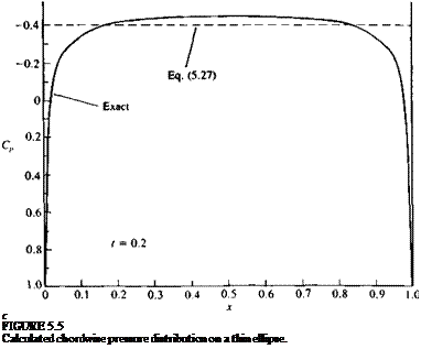
The pressure coefficient thus becomes
C„ = —21 (5.27)
 |
which indicates that the pressure coefficient is a constant. This result is plotted in Fig. 5.5 and compared with the exact solution obtained by complex variables (Van Dyke53 p. 52). The maximum of |—C„ is well predicted but the solution near the front and rear stagnation points is incorrect. As the thickness ratio decreases the pressure distribution becomes more flat with a smaller stagnation region and therefore the accuracy of this solution improves.


